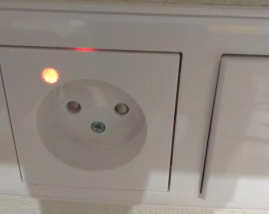
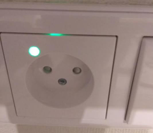
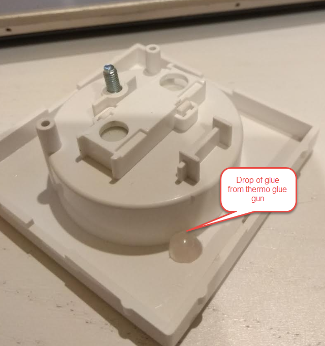
Unfortunately I can't open my ebay shop right now. While I'm trying to open it, you can buy this board here: https://www.ebid.net/eu/for-sale/arduino-ide-compatible-low-profile-220v-10a-relay-rfm69hw-433-mhz-radio-156694939.htm

Specification:
- Authentication security - Atmel ATSHA204A Crypto Authentication Chip
- External JDEC EPROM
- RFM69-HW (high power version) 433 MHz Radio transceiver
- ACS-712 current sensor. Range from 0,1 A up to 10 amperes.
- External JDEC EPROM
- Dualoptiboot bootloader. Implements over the air (OTA) firmware update ability
- Pixel LED SK6812mini
- Regullar LED can be directly connected
- External button connector with JST 1.25 мм connector
- Supply voltage 160-240 Volts AC
- The Digital and Analog pins are 3.3 volts
- Uncompromised Protection:
Overload varistor
Slow fuse
Thermal fuse
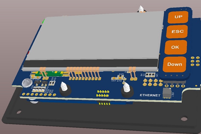
- Board Dimensions: Diameter is 55mm and Height is only 13mm
- FTDI header for programming
Pin out:
| Arduino Pins |
Description |
| A7, A8 |
Available ARDUINO analog GPIO / DIGITAL GPIO |
| D5, D3 |
Available ARDUINO digital GPIO |
| Check picture to see both Analog and Digital pins |
 |
D5 with 200 ohm resistor
connector and A2 as Relay button |
In case you do not like soldered SK6812mini
you may use here regular LED for Relay visulal feedback
 |
| A2 |
connected to JST 1.25 мм connector. Used as external relay switch in the sketch
 |
| A1 |
connected to ACS712 current sensor |
| A3 |
connected to ATSHA204A |
| D6 |
connected to Pixel LED SK6812mini |
| D7 |
connected to the 10A Relay |
| D8 |
Connected to CS FLASH chip (OTA) M25P40 |
| D9 |
connected to RFM69 reset pin |
| RFM69 antenna |
 |
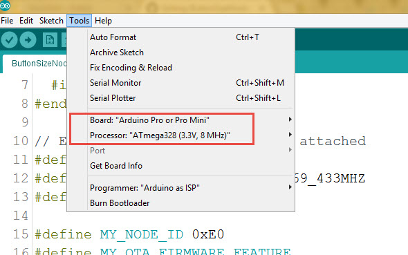
Arduino IDE Settings
How to use it as home automation (IOT) node Relay
wallSocketInsertableNode.ino is the Arduino example sketch using MySensors API.
Burn the wallSocketInsertableNode.ino sketch into it and it will became one of the MySensors home automation network Relay Node. The Relay could be controlable from a smarthome controller web interface or smarphone App.
To create Home Automation Network you need smarthome controller and at least two Nodes one as a Sensor, relay or actuator Node and the other one as “Gateway Serial” connected to the smarthome controller. I personally love Domoticz as smarthome conroller. Please check this HowTo to install Domoticz.
However, for no-controller setup, as example, you can use 3 nodes - first node as “Gateway Serial”, second node as the Mini Relay Box node and the last one as switch for the relay node. No controller needed then, keep the switch and the relay node on the same address and the switch will operate the relay node.
Things worth mentioning about the MySensors Arduino sketch:
| Arduino Pins |
Description |
#define MY_RADIO_RFM69
#define MY_RFM69_FREQUENCY RF69_433MHZ
#define MY_IS_RFM69HW |
Define which radio we use – here is RFM 69
with frequency 433 MHZ and it is HW
type – one of the most powerful RFM 69 radios.
If your radio is RFM69CW - comment out line
with // #define MY_IS_RFM69HW |
| #define MY_NODE_ID 0xE0 |
Define Node address (0xE0 here). I prefer to use static addresses
and in Hexadecimal since it is easier to identify the node
address in Domoticz devices list after it
will be discovered by controller ( Domoticz).
However, you can use AUTO instead of the hardcoded number
(like 0xE0) though. Domoticz will automatically assign node ID then. |
#define MY_OTA_FIRMWARE_FEATURE
#define MY_OTA_FLASH_JDECID 0x2020 |
Define OTA feature. OTA stands for “Over The Air firmware updates”.
If your node does not utilize Sleep mode you can send new “firmware”
(compiled sketch binary) by air. Here is the link on how to do it.
For OTA we use JDEC Flash chip where the node stores
new firmware and once it received and controlsum (CRC) is correct
it reboots and flashes your new code into the node
controller. So we define it is "erase type" as 0x2020 here. |
#define MY_SIGNING_ATSHA204
#define MY_SIGNING_REQUEST_SIGNATURES |
Define if you like to use Crypto Authentication to secure your nodes
from intruders or interference. After that, you have to “personalize”
all the nodes, which have those, defines enabled.
How to “personalize” nodes with encryption key.
You need both defines in the nodes you need to protect.
The Gateway Serial could be with only one of those
defines enabled - #define MY_SIGNING_ATSHA204 |
| #define AdafruitNeoPixel |
Enables onboard Pixel LED SK6812mini |
Connect the Relay to FTDI USB adaptor, Select Pro Mini 8MHz board and burn the wallSocketInsertableNode.ino sketch.
Done
The board is created by Koresh
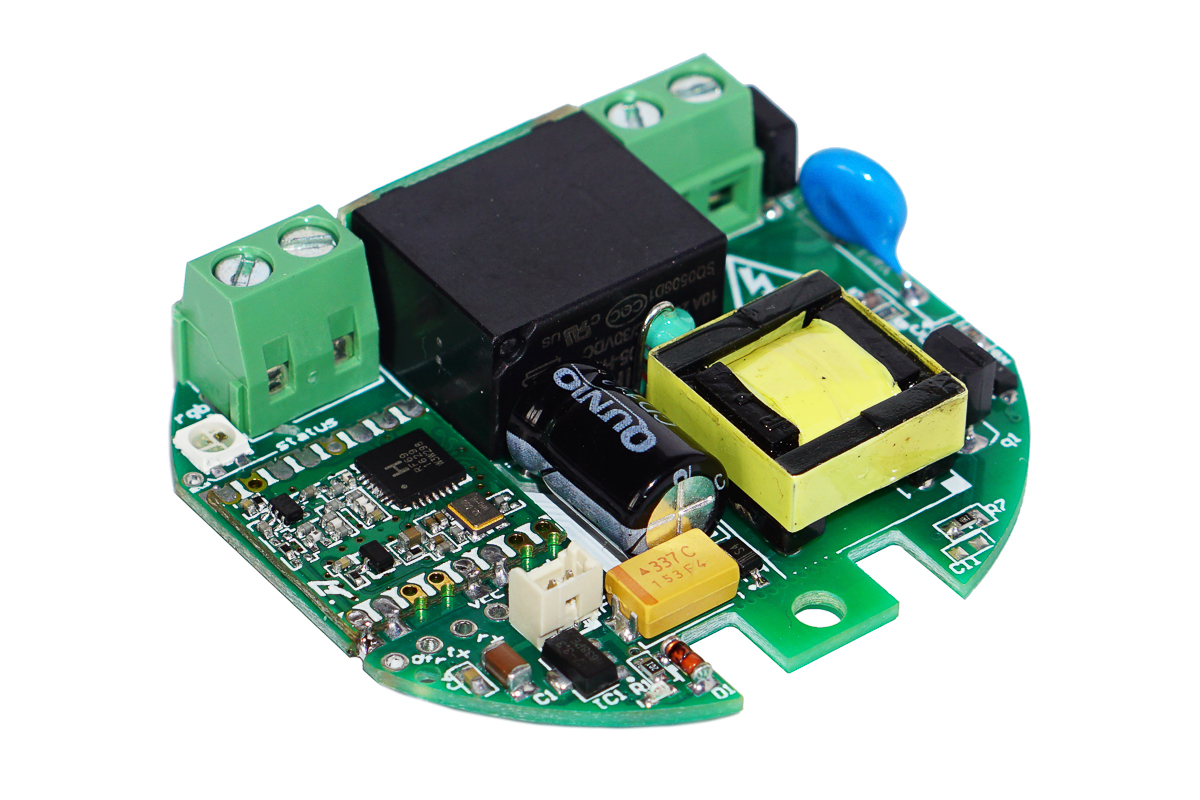
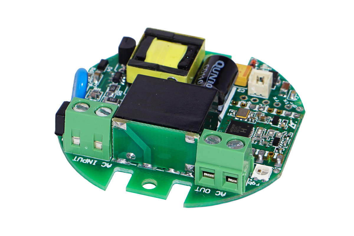
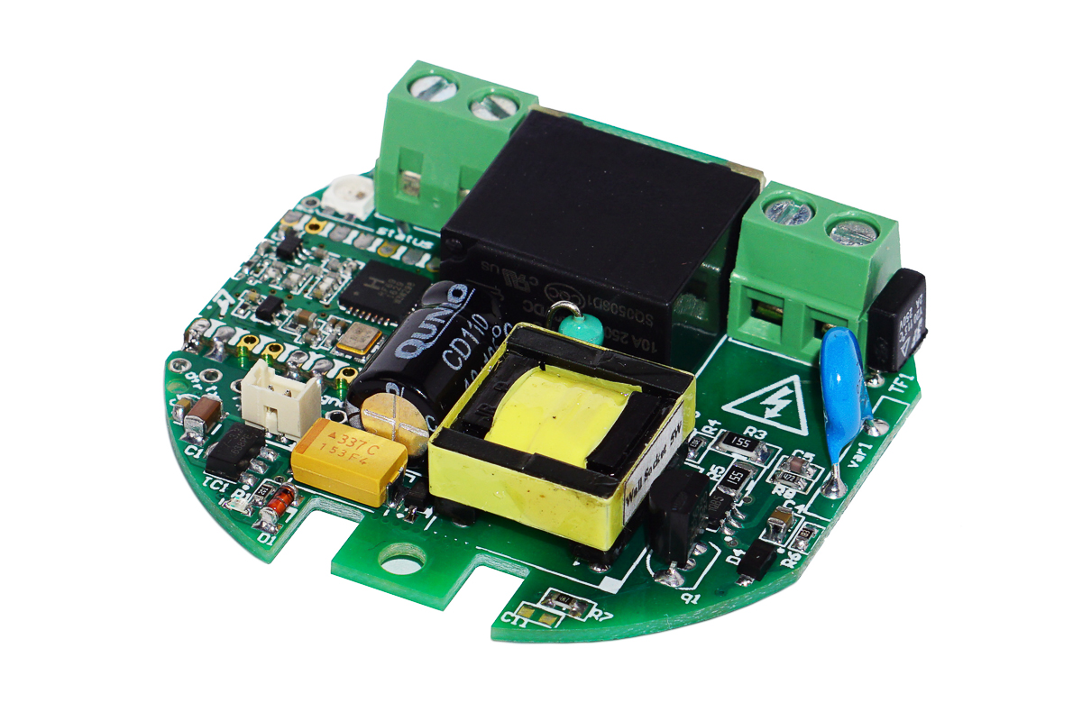
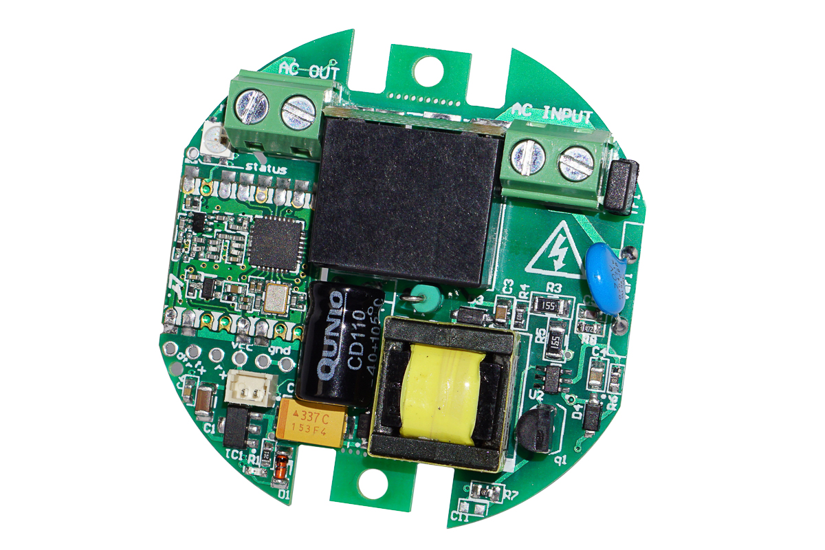
The board schematics Pdf link
P.S.
Always mind! if your Arduino code fails you need some backup plan. Put some candles and matches in your bathroom )))))... hope you understand. Start your automation wisely. Like auotomate your doghouse first. Then checkenshed and so on!!!
 Wall Socket Insertable Node:


