@Dwalt Thank you very much, now I understand better why the measurement of the voltage on input A0 was never good ..
jModule
Extension module with Arduino Pro Mini connected with nRF24L01 radio.
The goal of this project is to create a module for further use with "mySensors". The module must be as small as possible, easy to build and cheap.
**Build instruction **
- First prepare all needed elements:
jBoard
Arduino Pro Mini compatible board
nRF24L01 radio
AMS1117 voltage regulator
4,7uF capacitor
1x9, 1x2, 1x1 goldpin headers
1x6, 1x6, 1x2 angular goldpin headers
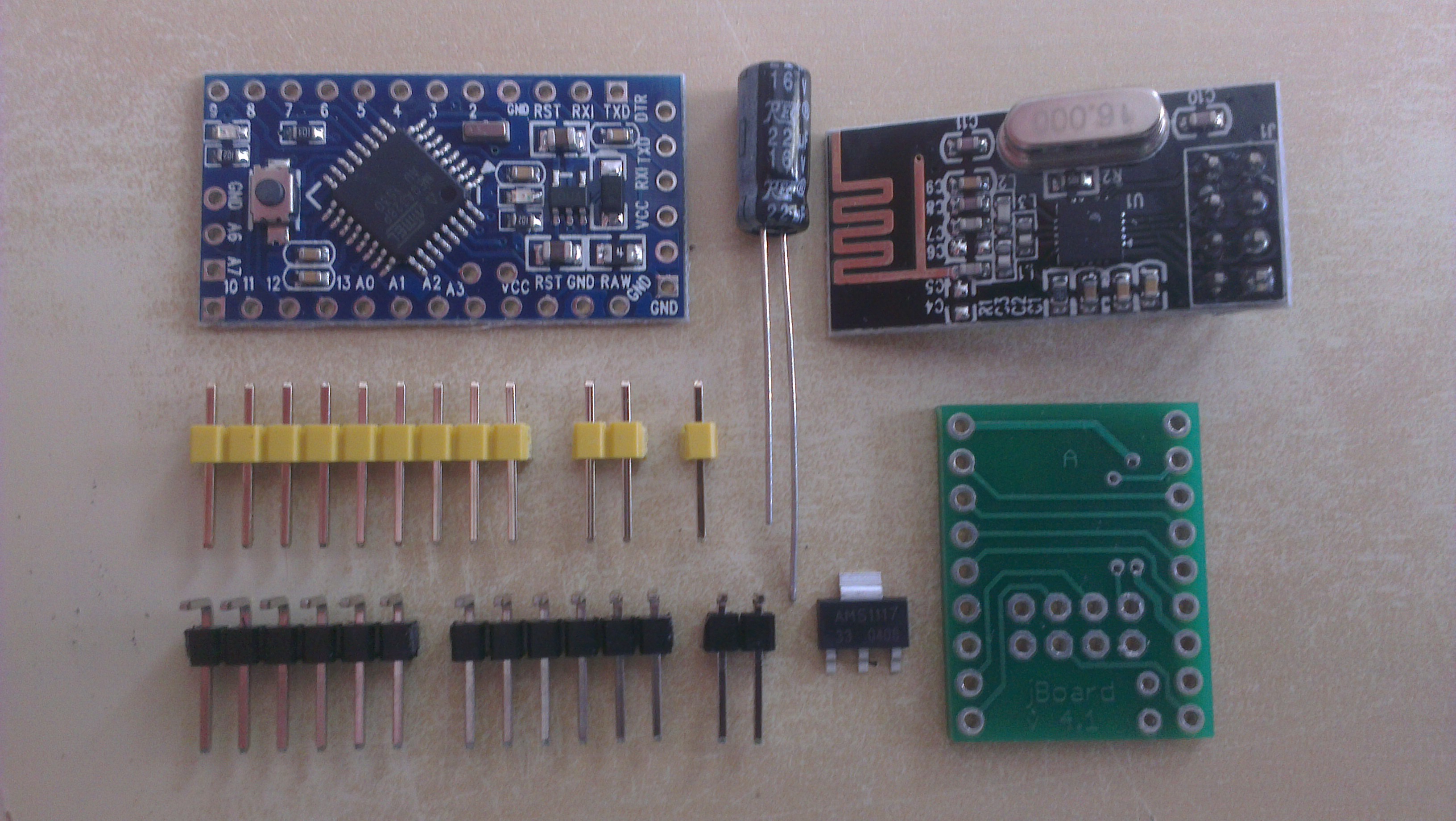
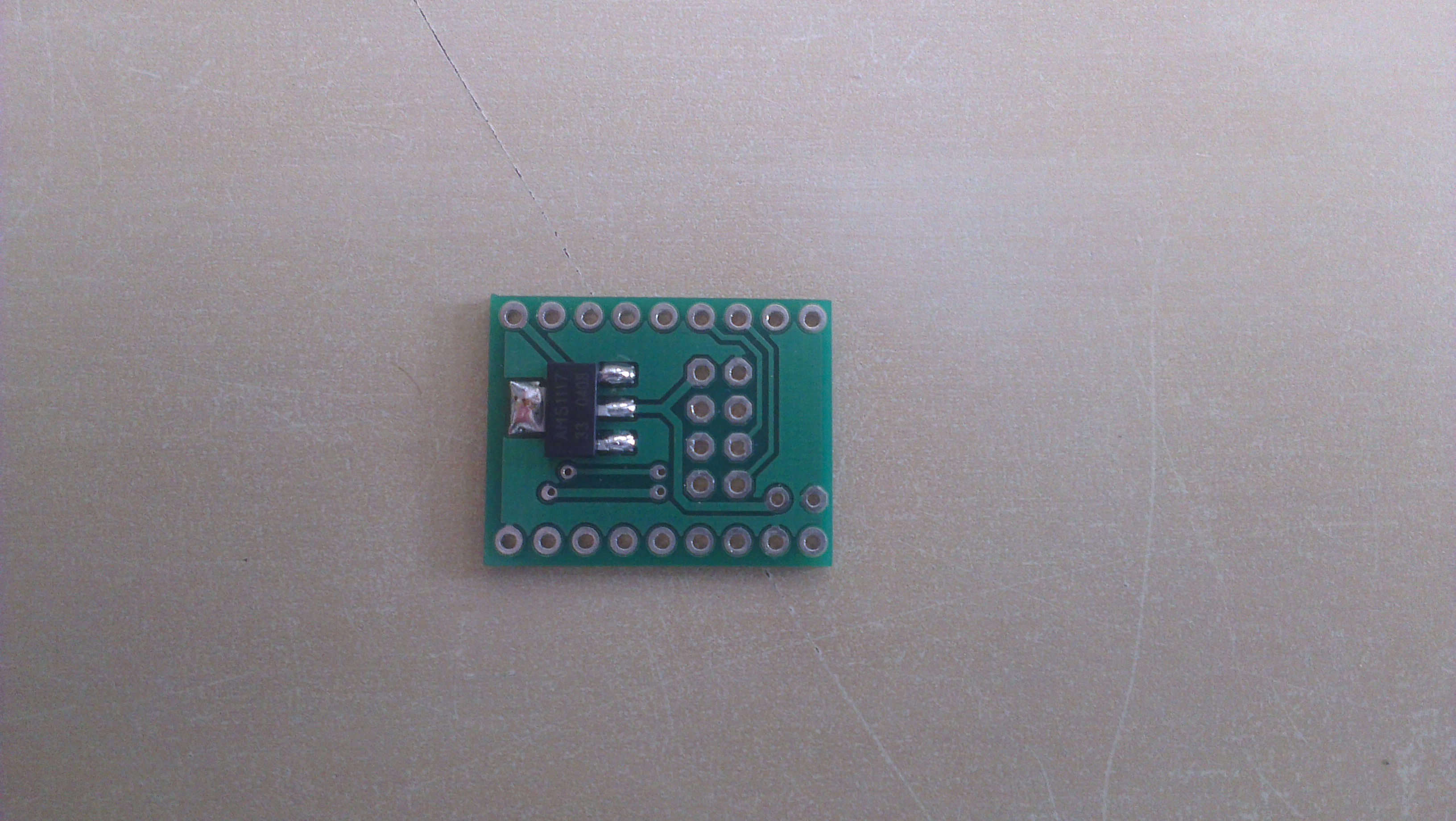
Solder AMS1117 voltage regulator to jBoard. If you use 3v Arduino Pro Mini skip this step. Instead of this make a connection between Vin and Vout pads for the regulator on the jBoard.
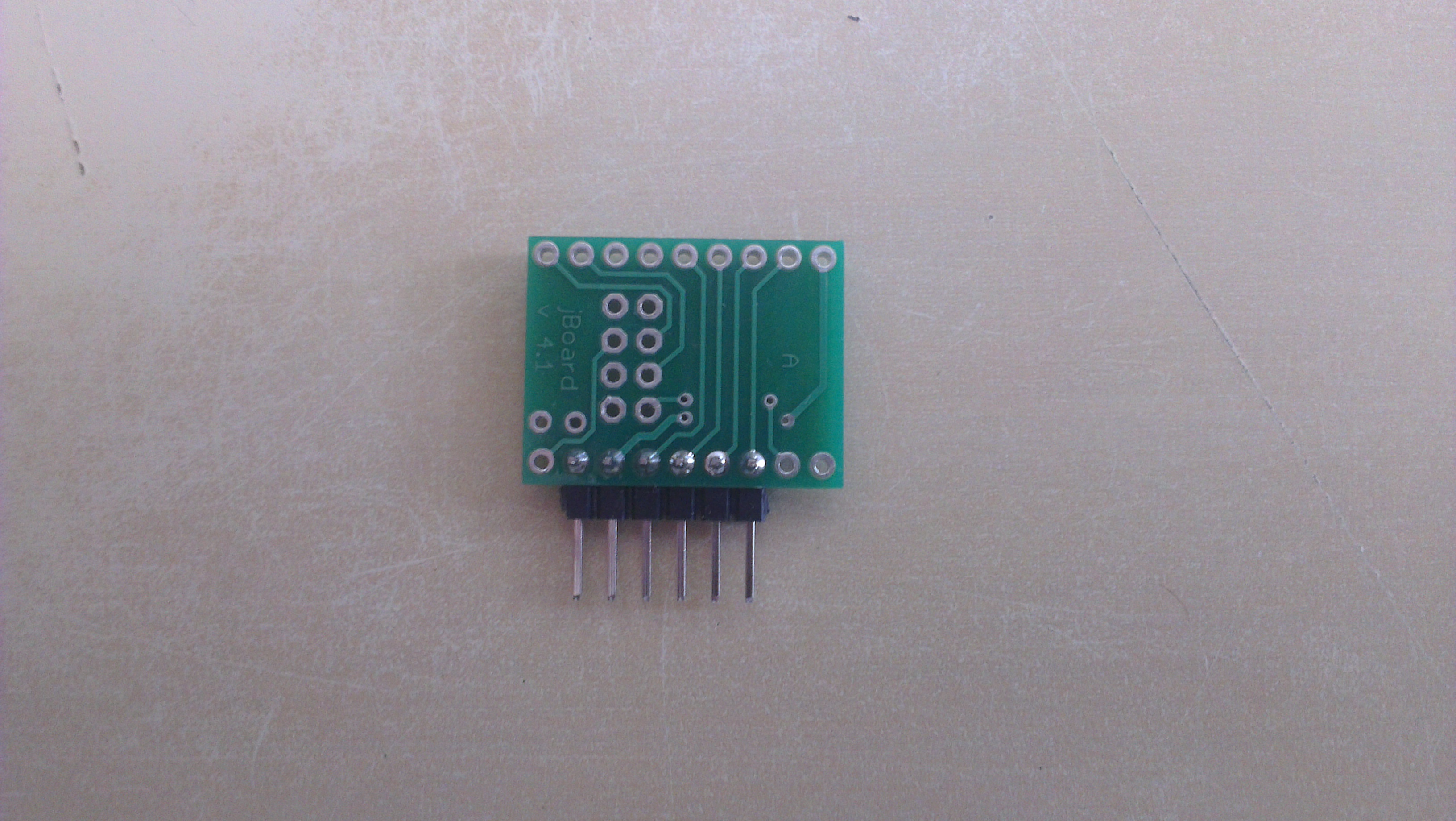
Solder 1x6 angular goldpin header to jBoard.
Solder 1x2 and 1x1 goldpin headers to jBoard.
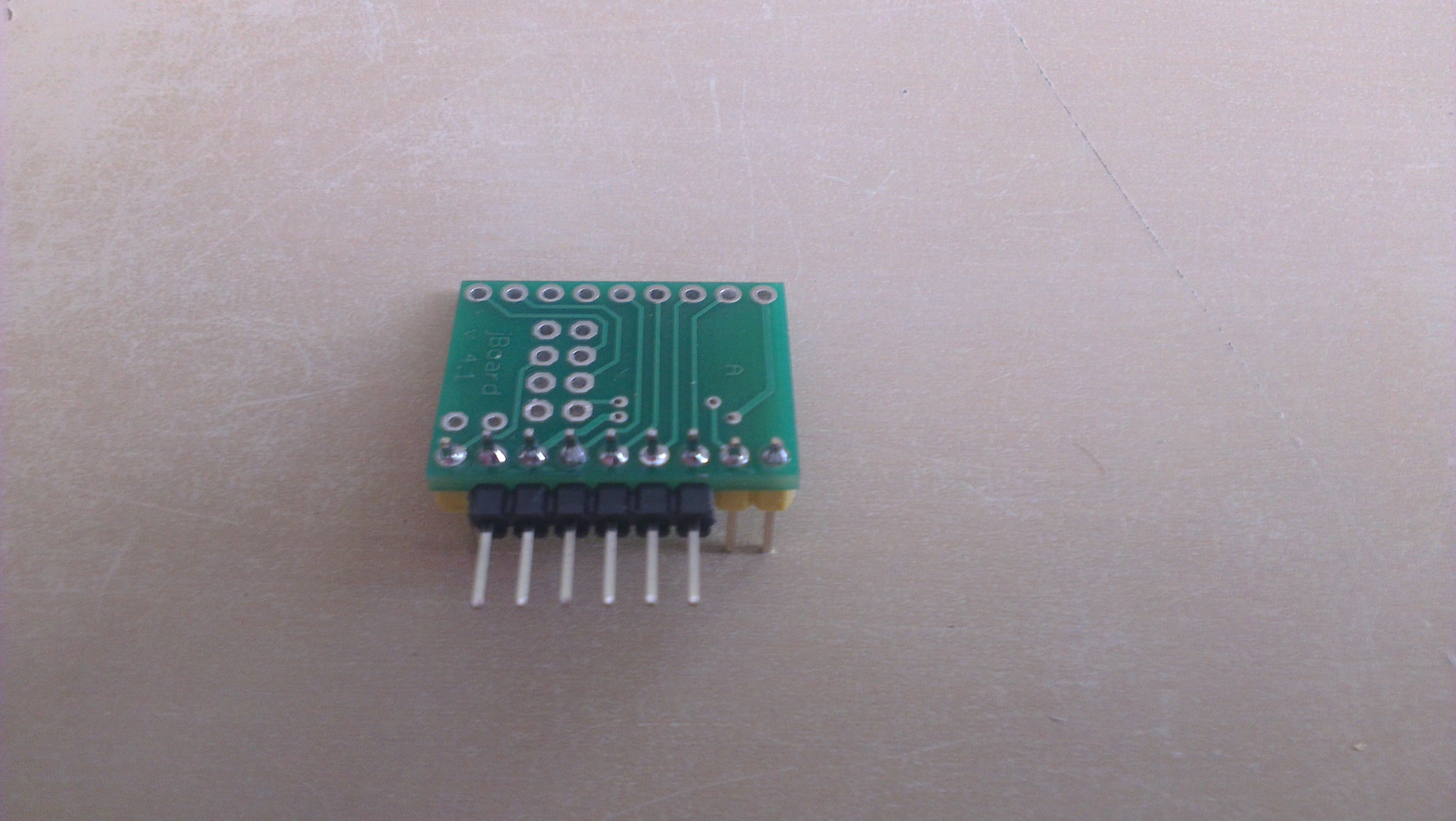
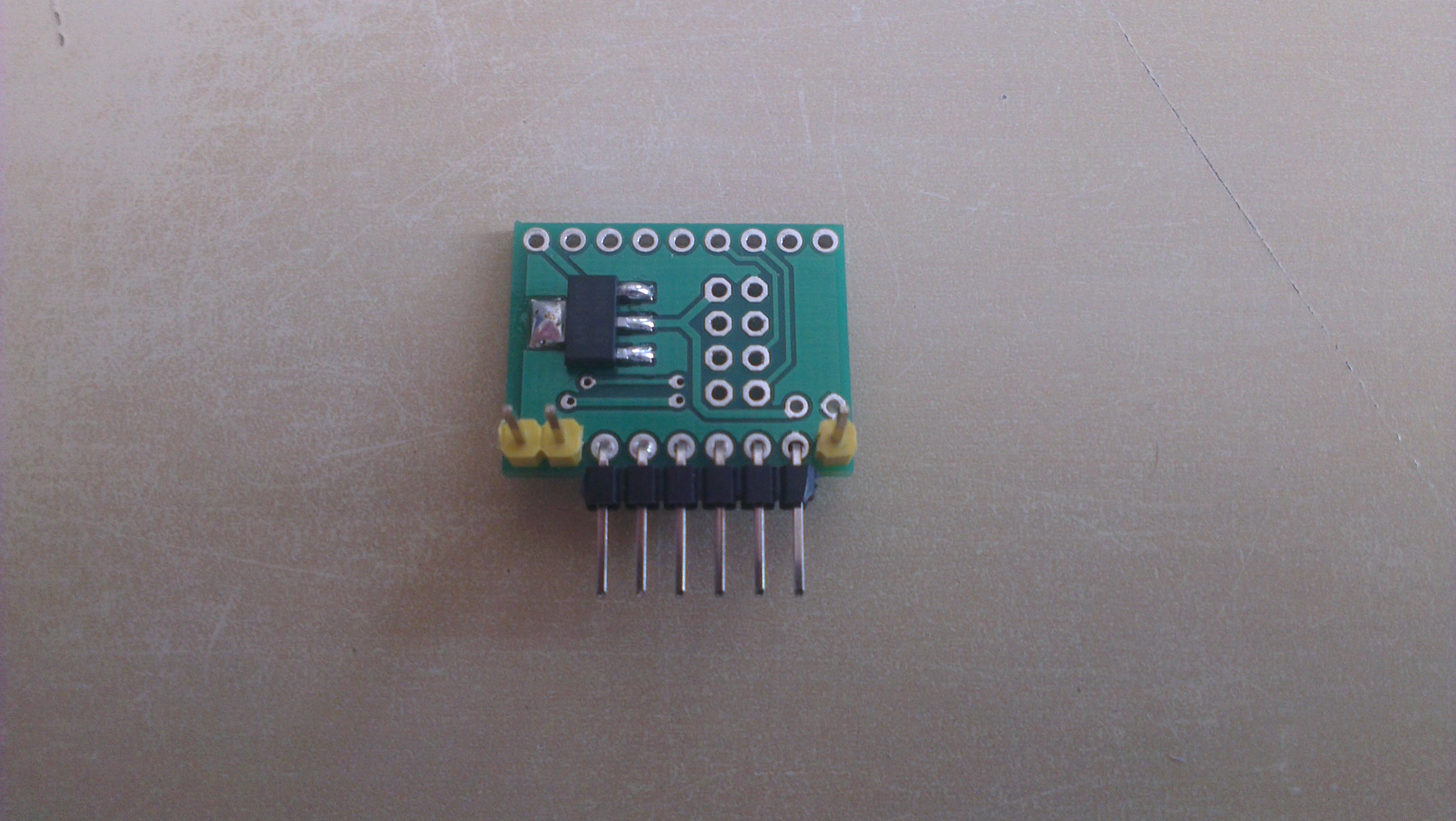
Solder 1x9 goldpin header to jBoard.
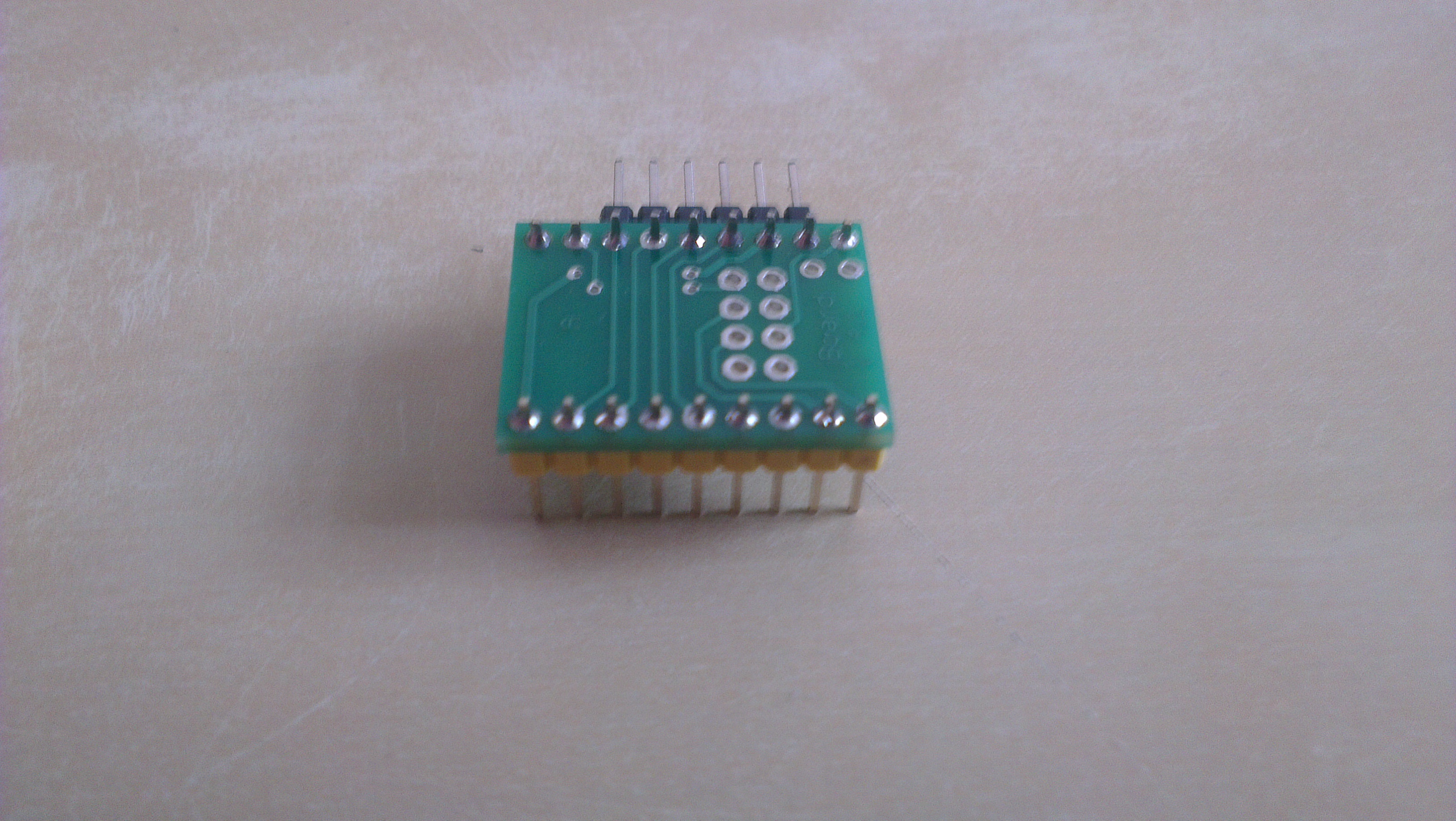
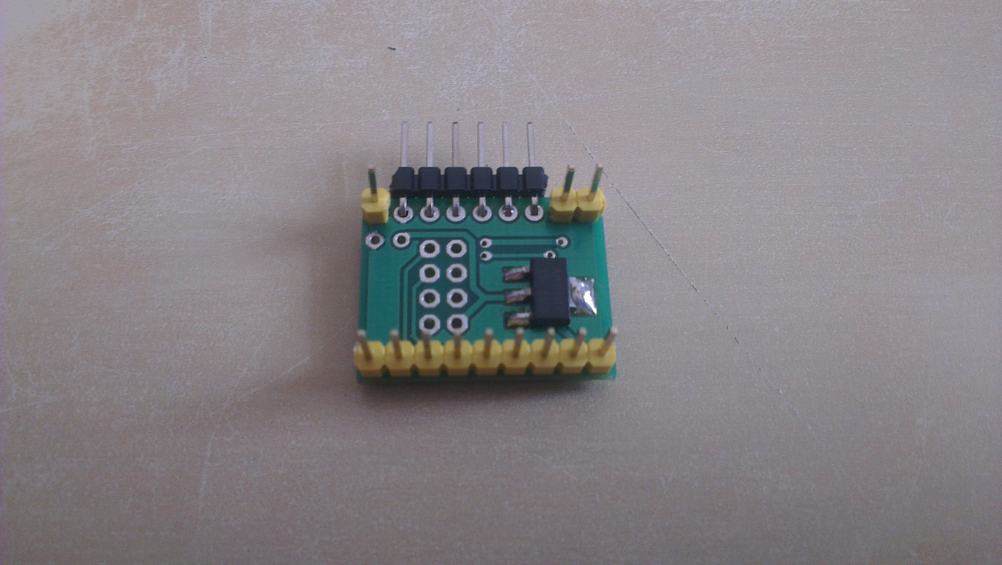
Smooth goldpin headers.
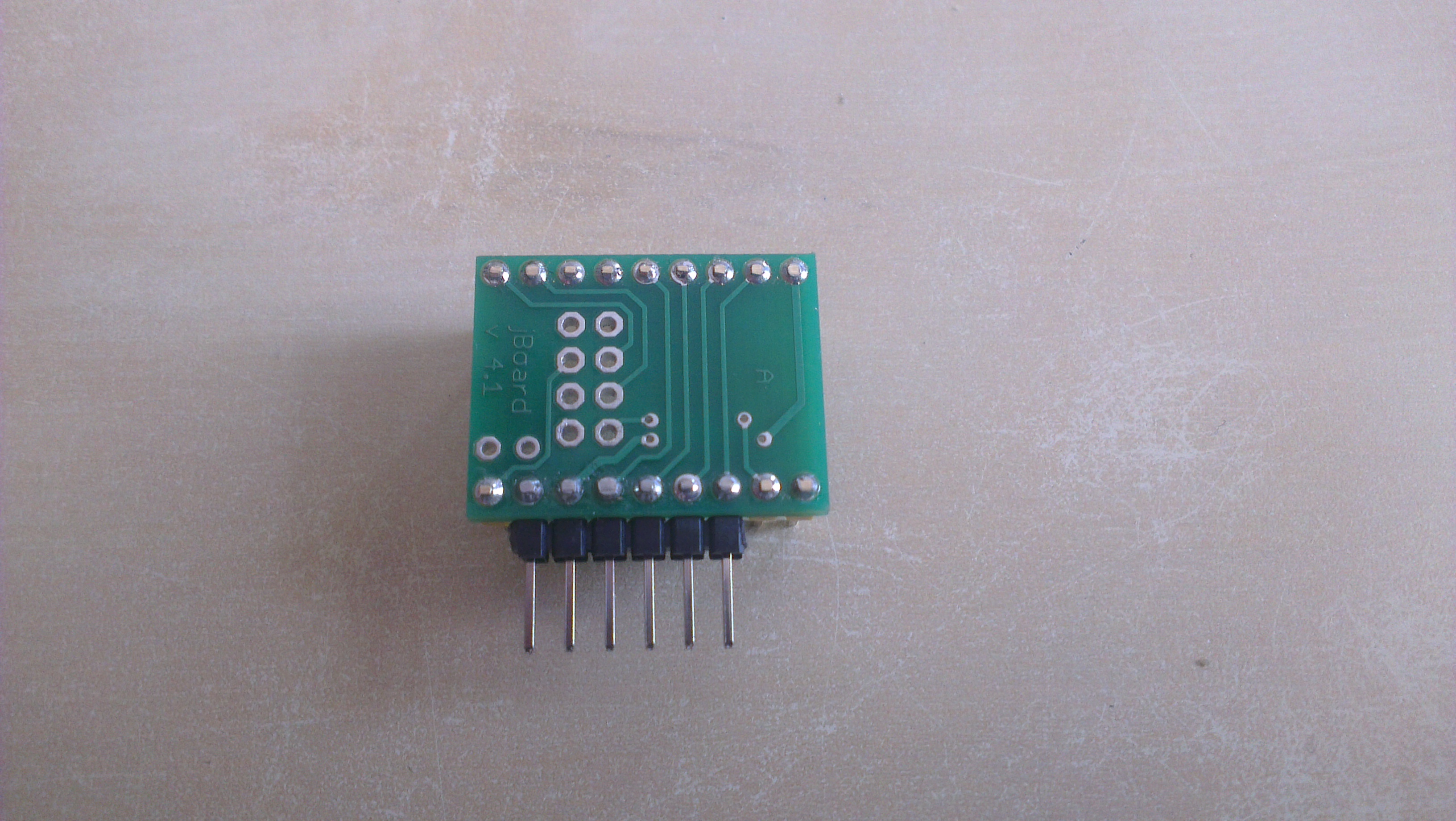
Remove a plastic distance from nRF24L01 radio and using an adhesive tape make an electrical insulation.
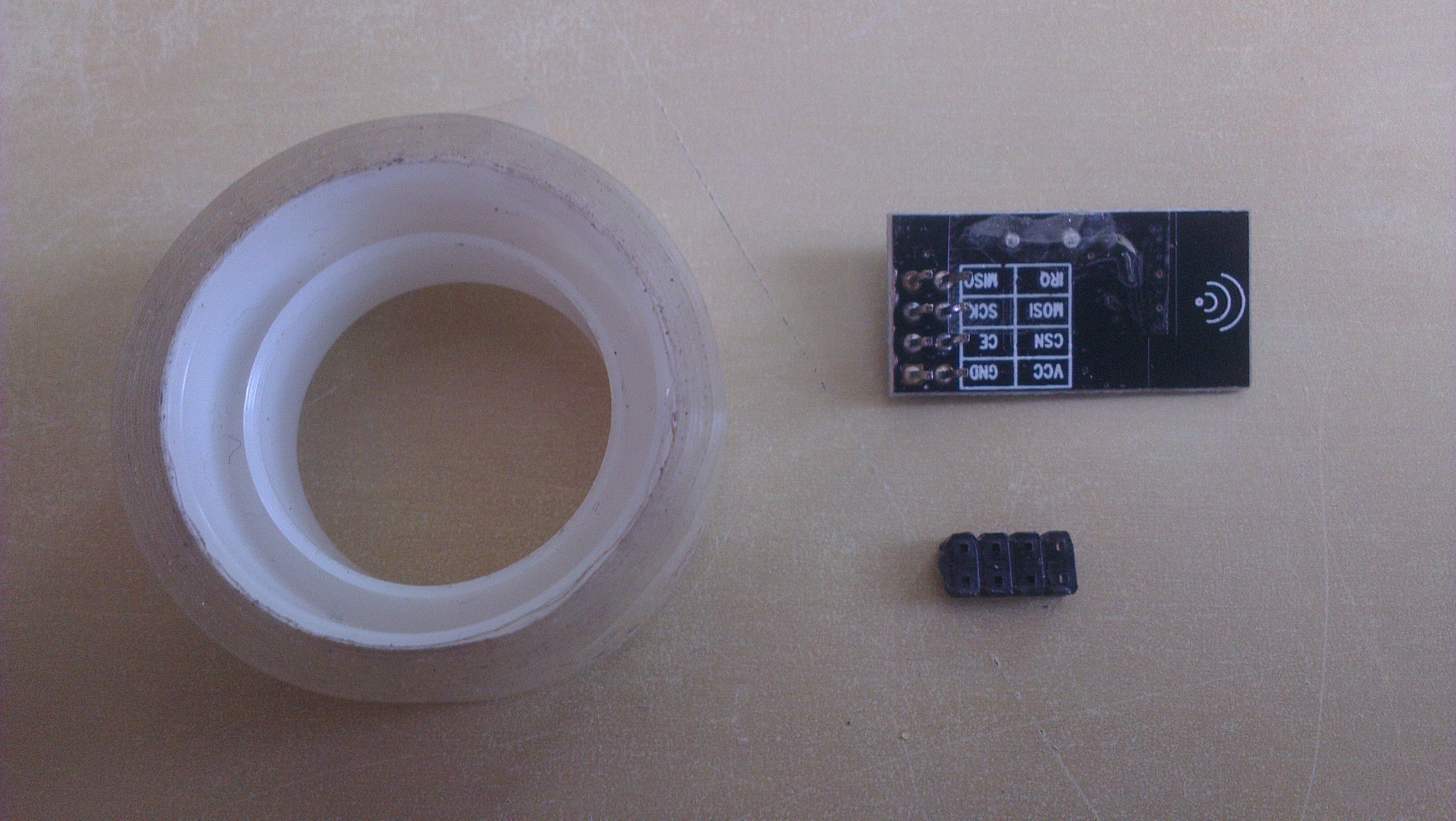
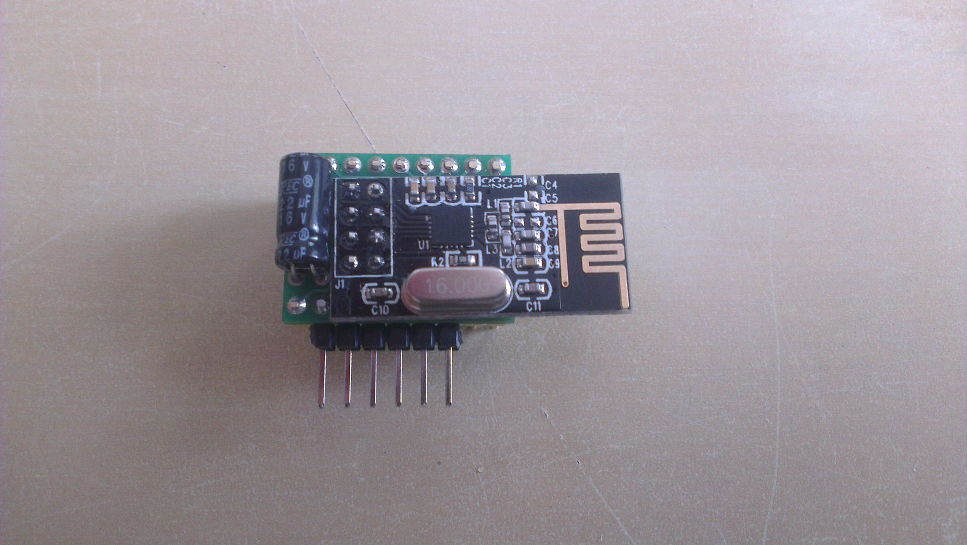
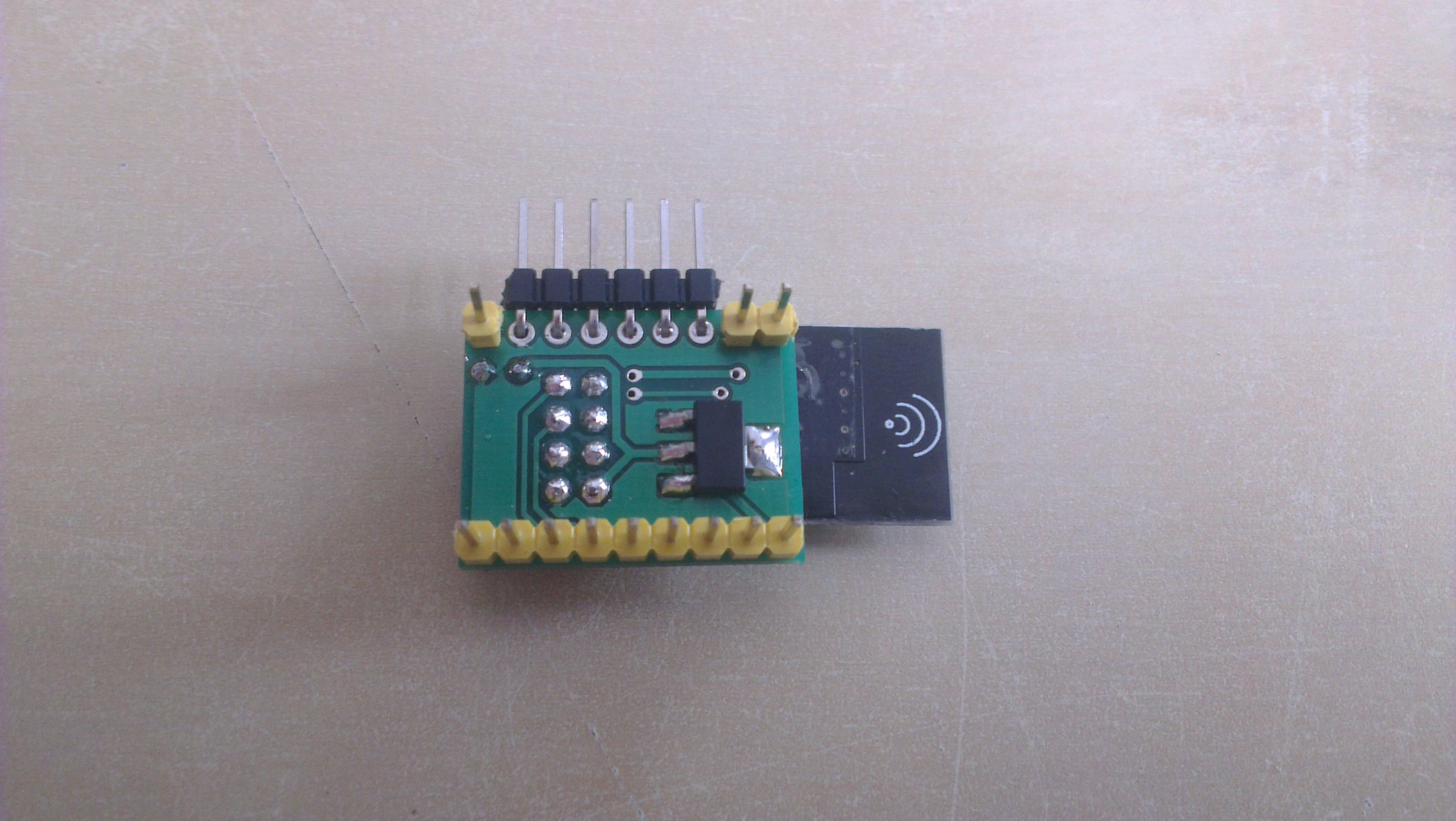
Solder nRF24L01 module and decoupling capacitor to jBoard. Cut off protruding headers.
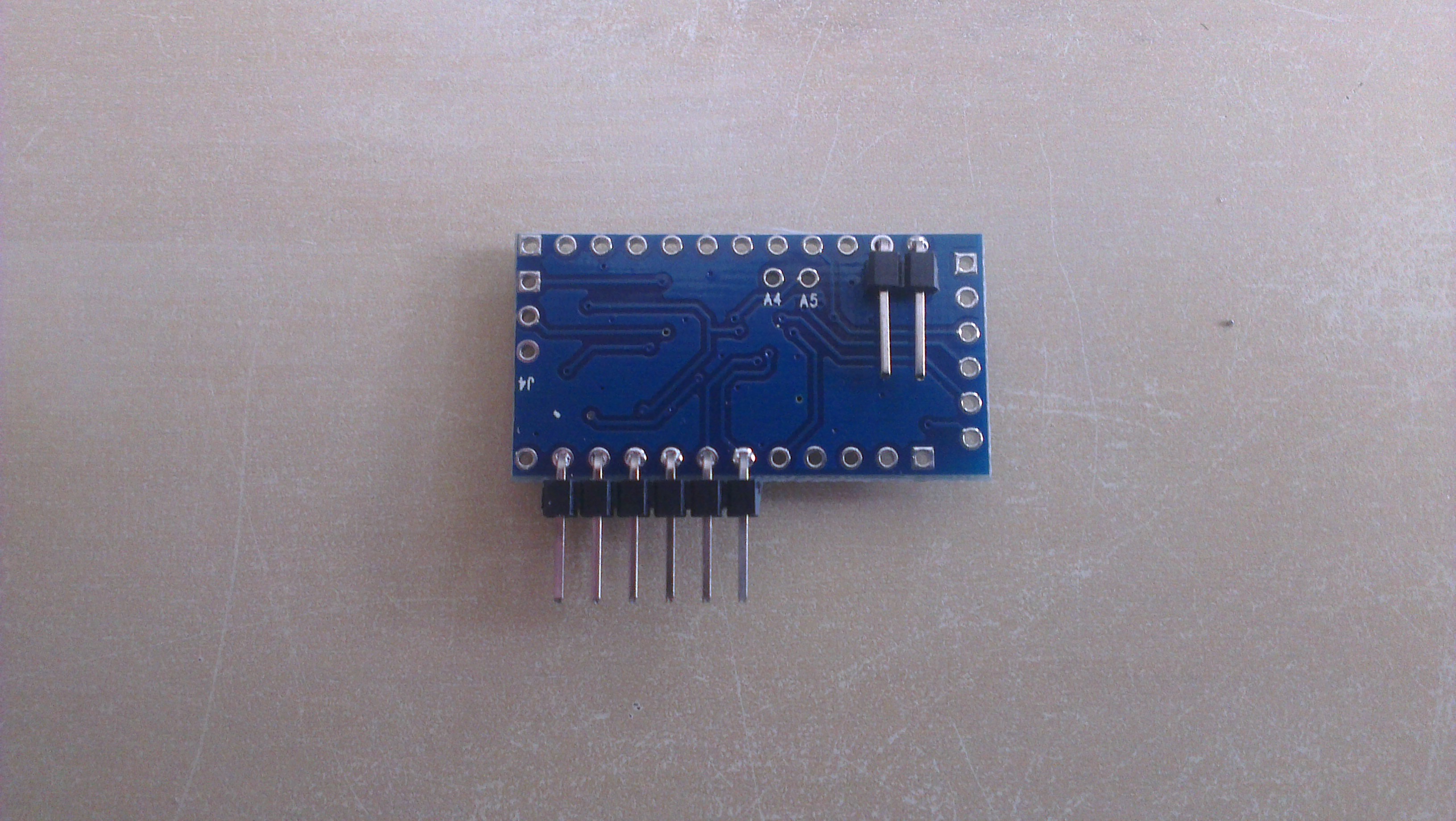
Solder 1x2 and 1x6 angular goldpin headers to Arduino Pro Mini (RAW, GND and 3...8 pins).
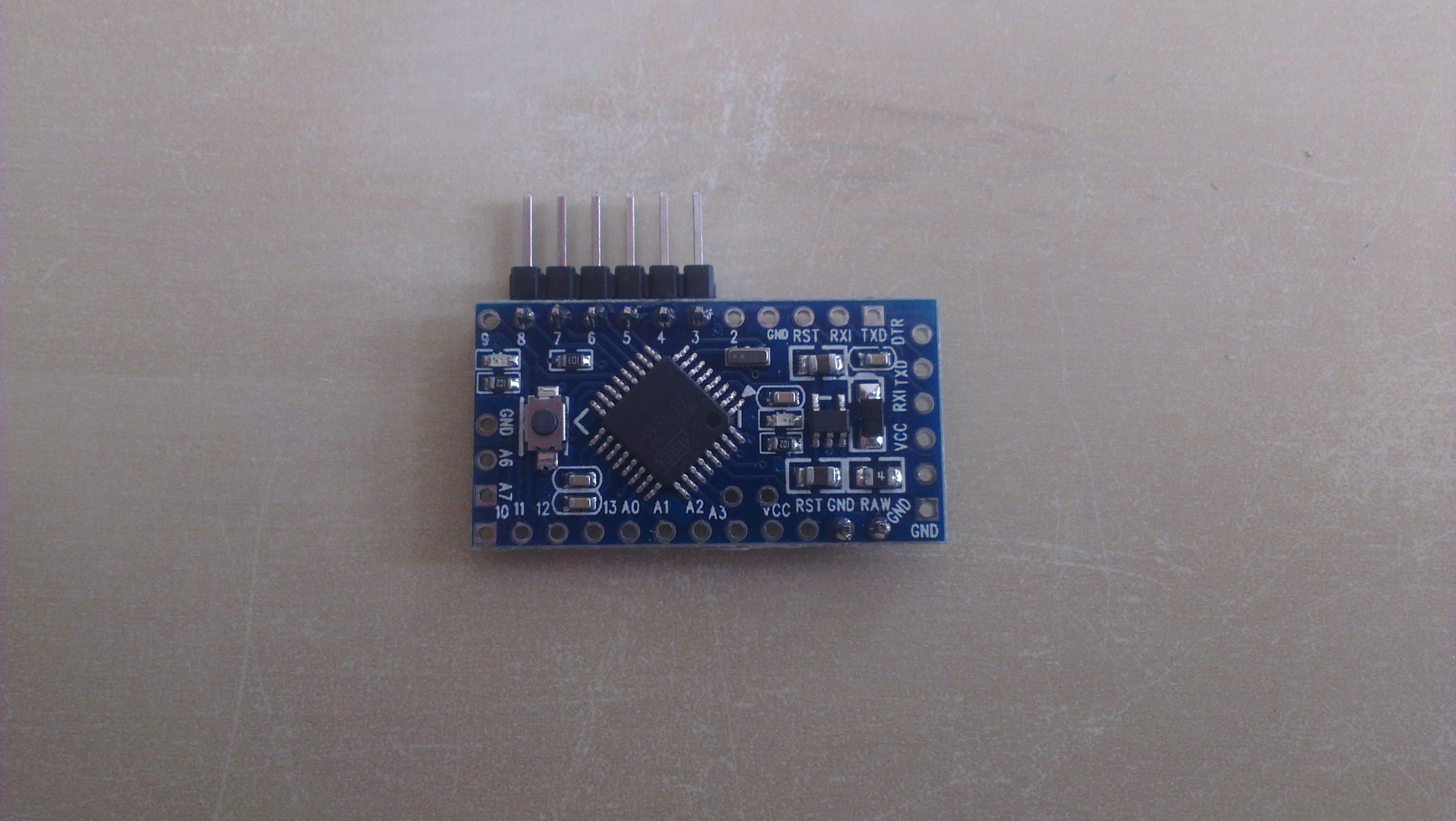
Solder jBoard to Arduino Pro Mini. Cut off protruding goldpin headers and next smooth the headers.
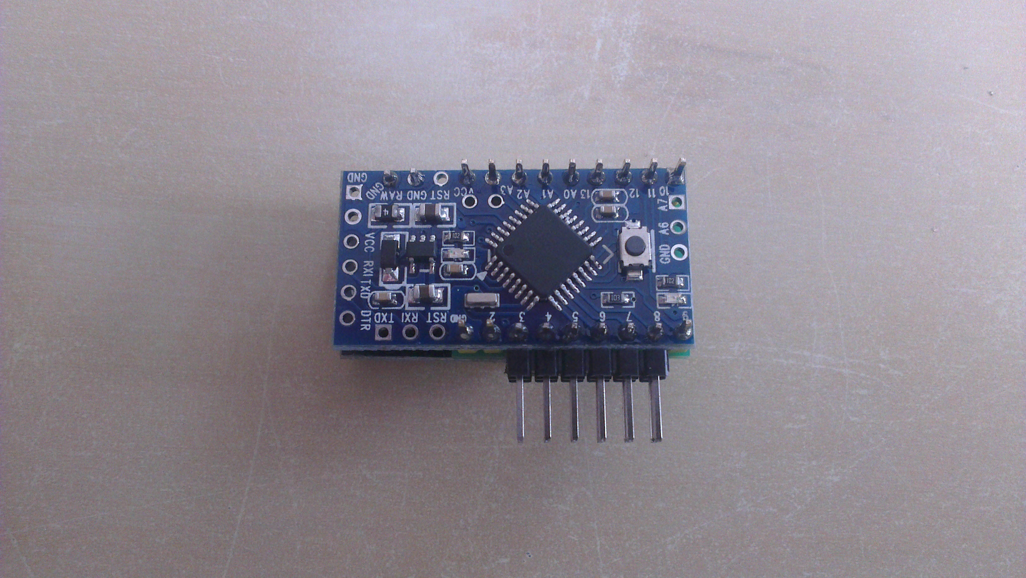
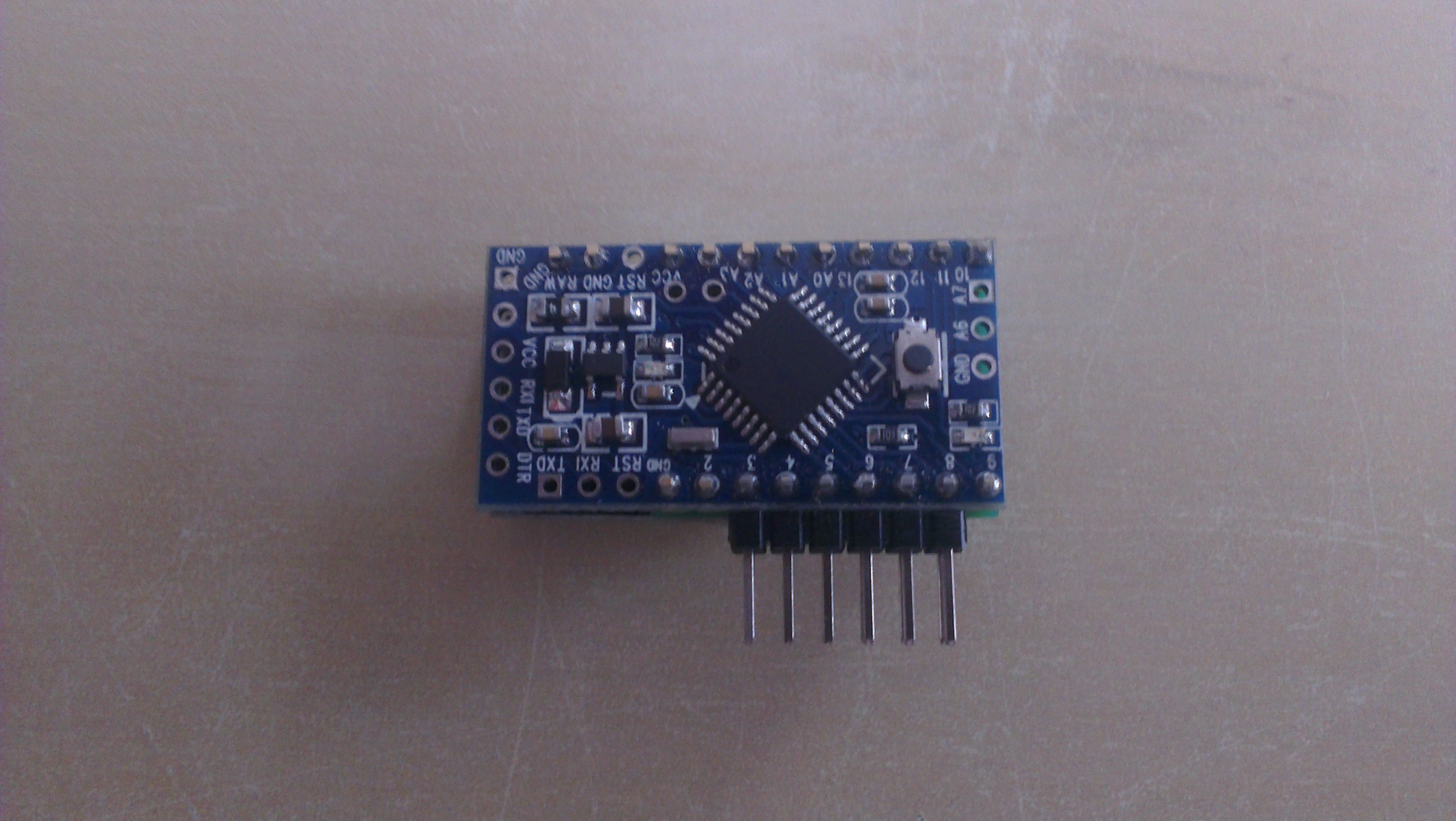
Done :). The module is ready to talk with your "sensor projects".
10 IO pins(3...8, A0...A3) plus one GND pin and one VCC pin are located on one side.
Only a 2x6 female goldpin header on the edge of your board and 2 wires from a power supply are needed to use the module.
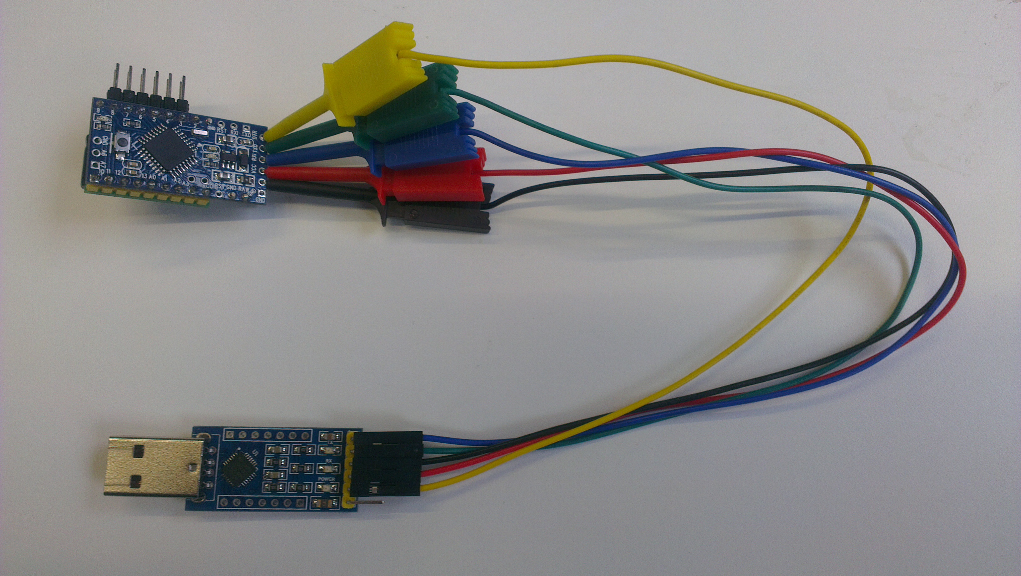
Easy to access serial interface for programming.
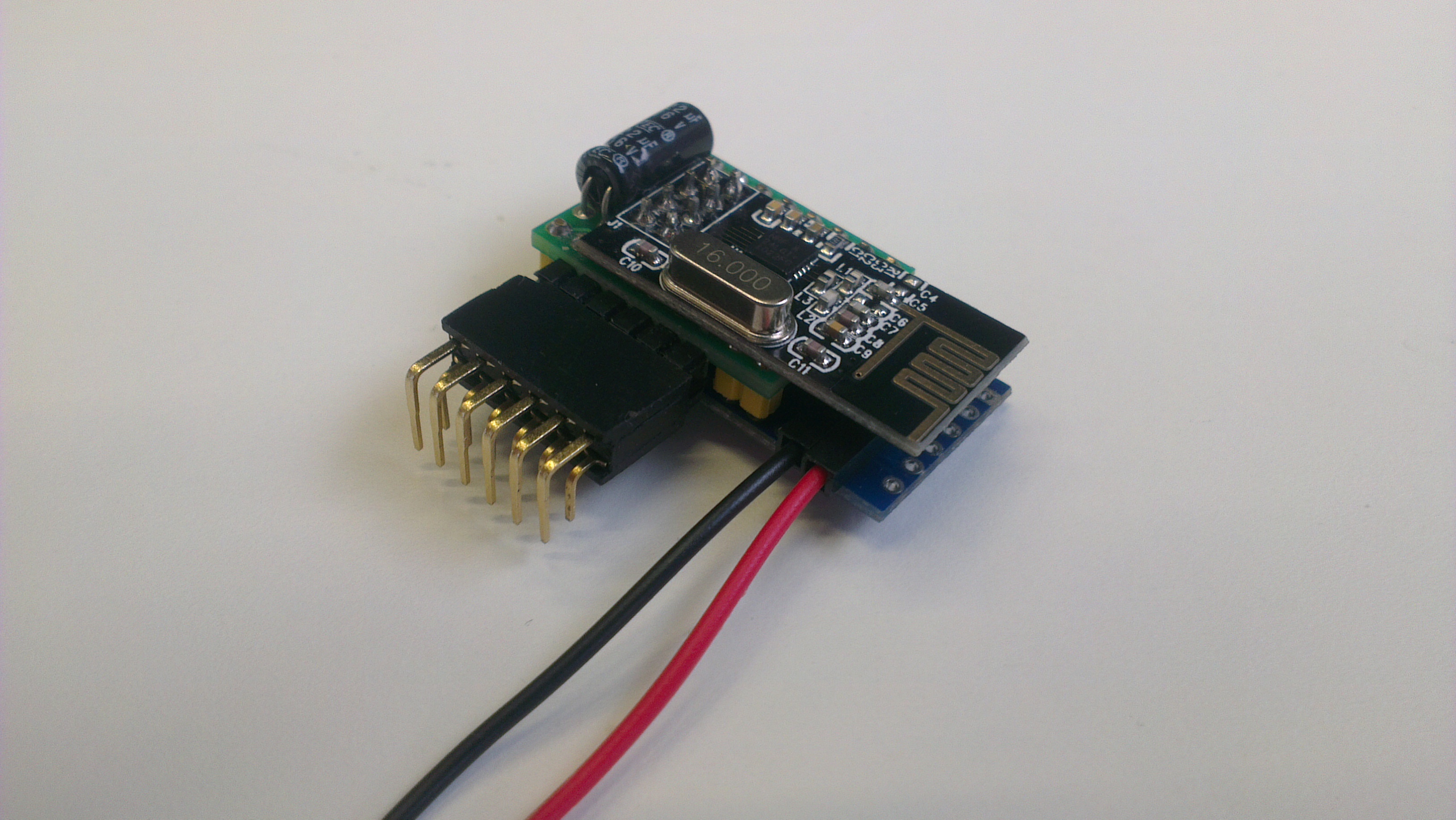

 jModule
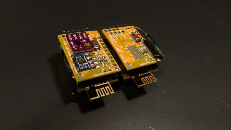
 Made a temperature/humidity/light sensor and a door sensor.


 )
)