-
Orange Pi is a controller and not a gateway. If you are suggesting you want to use the 5v adapter to power both controller and gateway I can not answer you. It might work but in the same time it might be to weak or to much interference. Try! If you get alof of random freezes and/or bad network communication you might want to seperate them
-
It might work - but using the nrf24l01+ amplified requiers some more juice than then pro mini/uno/nano can handle so I suggest using a power in with a good voltage regulator (that can provide high current) and then split of to each unit.
I recently build and updated my gateway for Mysensors to the new version 2.0 and wanted to share my experience and pictures if anyone in the future are going for the same build.
Also along the way I have been working with Mysensors i learned a couple of things i wanted to implement in the new gateway.
As i heard many times from petewill, and I totaly agree - build modular. I have learned that working with DIY you always want to enchance or exchange something, do something better and if you build everything so its easy to change parts it will help you alot in the future.
AWI showed some great tips with metalic cases, and I have also experience better radio performance using a metalic case. Don´t forget to ground the metalic case.
Using a nrf24l01+ with external power supply (or not powered from the arduino) to enhance range and staility.
Well, here we go:
I got a 100x100x43 cm aliminium case from ebay and here is my first tip - dont buy to small case! I was even thinking buying this case - well here is plenty with space... NOPE! (See pictures below). If you are going to build modular - expect it will take up some space.

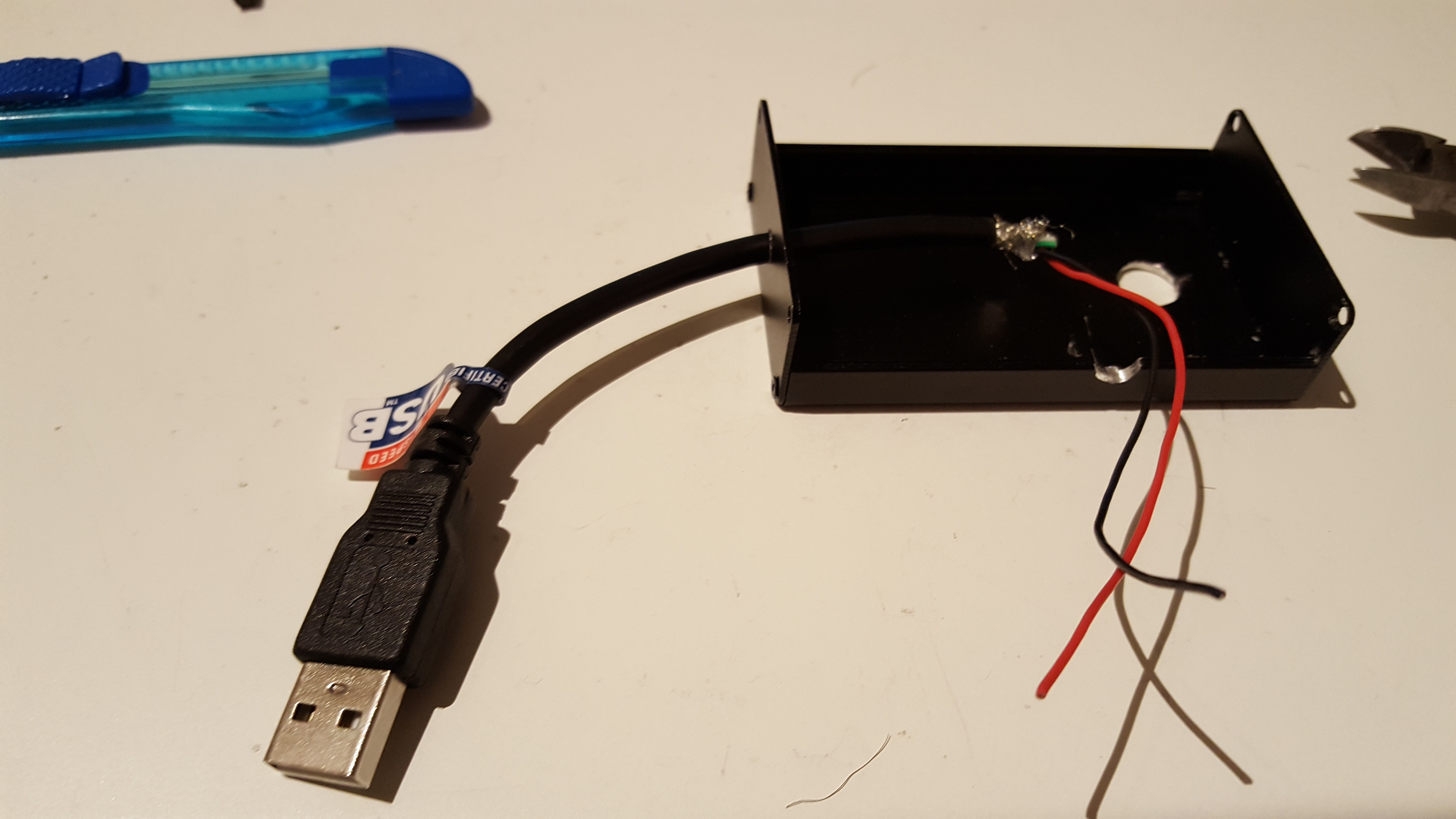
I planned everything out and cut the case for ethernet jack, power in, leds and a on/off switch. Hot glue is great! I glued the ethernet module to the bottom of the case after adding som insulation tape between the module and the case.

Before adding all components to the case, do a breadboard layout first. Like always, it didnt work the first time - and after checking my radio I had to go for a different one - you will not regret it.

My first "module" is the leds, one 5v in pin, leds, resistors and 3 leds out for the RX/TX/ERR pins.

I screwed my power switch to the case, and soldered pins to the switch. Now i made my second module, a "power" pcb with 5V. 3.3V and GND pins. As you see in the last picture there isnt much room left after all wires are added.

I uploaded standard sketch from MySensors lib. I excluded unclusion button since i use Domoticz.
Wiring is the WizNET (W5100) Ethernet module and leds is from Advanced Gateway Options
Finised and working great.


