MySFreezer


Description
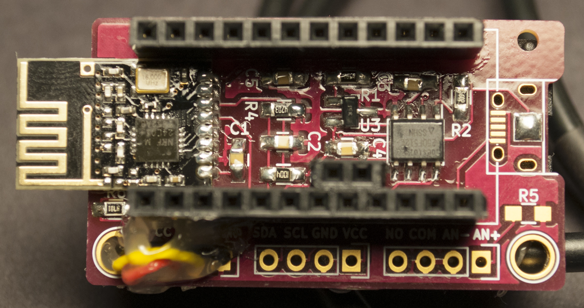
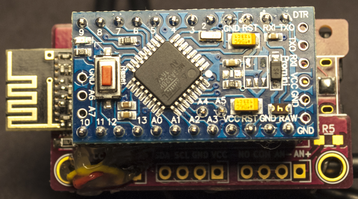
MySensors sensor node aimed to monitor sensitive lab equipment, especially ultra low temperature -80°C freezers.
4-20mA sensor
4-20mA sensors are commonly available via a plug connector on the back of recent -80°C Freezer. This requires a 47Ω resistor in R5. Connecting PCB "An-" and "An+" to a 4-20mA sensor will allow you to monitor your -80°C precisely without having to install anything inside the freezer.
Alarm relay
Alarm relays are commonly available via a plug connector on the back of recent -80°C Freezer. They are also often present for industrial fridges, incubators, etc. Any of these can be monitored and will wake up the device when alarm is triggered. Code is provided for Normally Open relays (circuit is closed when alarm is triggered) as they are the most commons, but a normally closed relay can also be used by updating the code. Connecting PCB "NO" and "COM" to an alarm relay will allow you to monitor the alarm state of the device.
I2C sensor
You can add extra I2C sensors if you need to expand the monitoring capacities of this PCB, or simply for extra versatility. You will need to update the code to add support for your I2C sensor. Exemple: add an Si7021 sensor and power the PCB via a USB wall charger and you can monitor a cold/hot room temperature and/or add a radio repeater.
1-Wire sensor / Thermistor probe
To monitor equipment lacking a 4-20mA output you can add a DS18b20 sensor on the 1-Wire port. This requires a 4.7kΩ resistor in R6. Optionally by switching R6 to a higher value (ex: 10kΩ) you can update the code to use a thermistor probe by plugging it between "1Wire" and "GND"
Ordering
Gerber files are included so you can order these PCB at your favorite PCB fab house and solder the few components yourself. For an easy ordering process you can directly order these PCB without having to do anything else:
- PCBs.io 4 for $6.78, black 1.2mm PCB, ENIG finish.
- OSHPark.com 3 for $8.55, purple 1.6mm PCB, ENIG finish.
Assembly
If you plan to power this node by a battery it is advised to first prepare your arduino pro mini according to MySensors battery powered sensors specifications (removing Vreg and power indicator LED). You may also want to change your BOD fuse settings. Do not remove the voltage regulator if you are powering the sensors using a USB wall charger, it will be used to power both arduino and radio module.
If you are using a battery holder start by soldering all SMD components except the radio module. Continue with arduino pin headers, trim them as close as you can of the PCB. Then solder the battery holder and if you need trim the negative pin to be flush with the PCB. Finally you can carefully add the radio module.
Optional components
Resistors R5 and R6
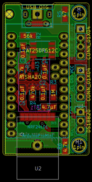
- R5 is required if monitoring a 4-20mA sensor. For most accurate readings this resistor should be 47Ω with a <1% tolerance.
- R6 is only required if using a 1Wire Dallas sensor (4.7kΩ) or a thermistor probe (10kΩ or more depending on your thermistor)
Capacitor C5
Only required while monitoring an Alarm relay. Prevents static noise to be detected as an alarm.
Dual power mode
You can run this node using batteries, a CR123 battery holder can be mounted on the PCB, using + and - pins of the PCB. It is also designed to use a micro USB connector as power input, any old USB phone charger will do.
Battery monitoring
If using a battery to power the sensor current battery level can be sent to the controller if R3, R4 and C5 are installed.
ATSHA204 module
For security reason you can add a CryptAuthEE SHA256 chip. This will allow you to sign messages and will secure communications between the node and your gateway (this is not encryption, just signing). If you only control lights, fan, or other non-essential hardware you probably don't need to bother with this chip. Signing can also be done at the software level, without the chip if you decide to add this function later.
Eeprom module
This module is only used to perform OTA updates on the node. If you don't plan to use this feature you can also skip this chip. You will also need to burn a compatible bootloader to your arduino (DualOptiBoot)
Arduino
Included program(s)
MySFreezerNode_4-20mA
Will monitor temperature using a 4-20mA sensor. This is calibrated for most of -80°C where 4ma equals -100°C and 20mA equals 50°C. You can change this accordingly to your device specifications by updating the line "temperature = map(voltage, 225, 875, -100, 50);" in the code. While in MY_DEBUG mode you will also have access to the ADC level to perform a fine tuning.
MySFreezerNode_DS18b20
Will monitor temperature using a DS18b20 temperature probe. If measured temperature is >-10°C then a software alarm will be activated. Temperature is defined by "TEMPERATURE_ALARM".
Revision history
Version 1.0: Initial release.
