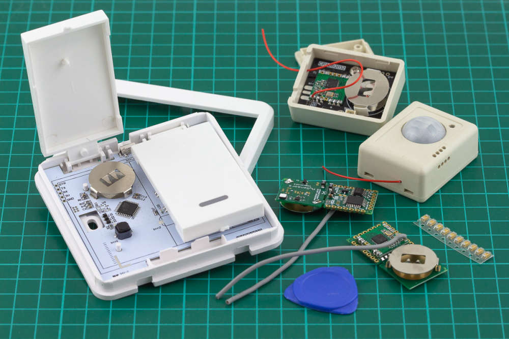
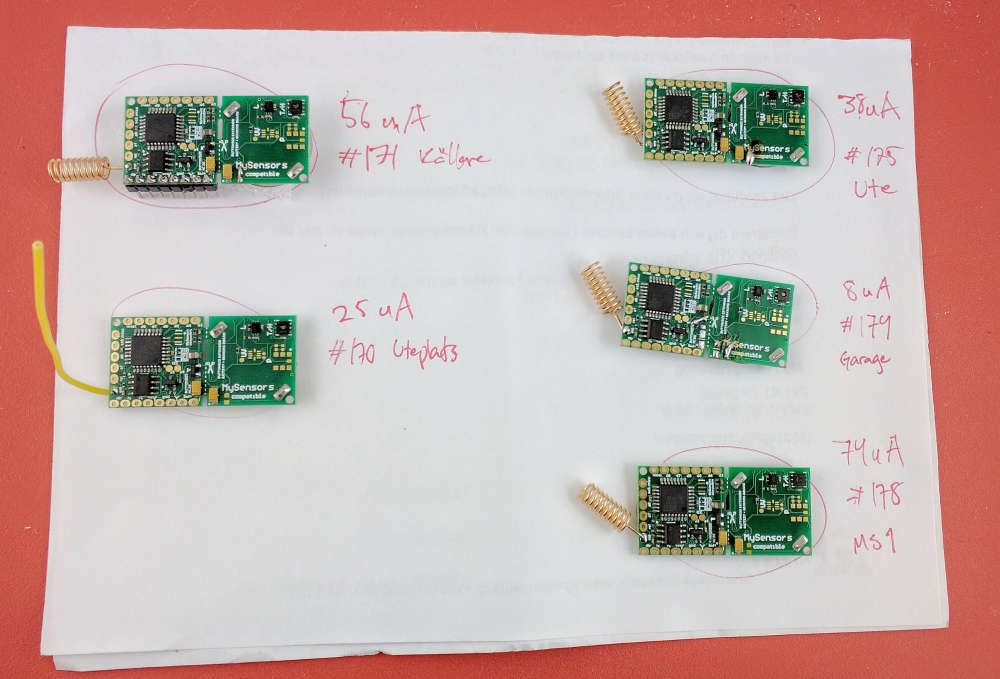
@mahesh2000 https://www.openhardware.io/view/299/Button-size-radionode-with-sensors-swarm-extension
Button size radionode with sensors swarm extension
GitHub:
License:
Attribution-ShareAlike (CC-BY-SA)
Created:
8 years ago
Updated:
about a year ago
Views:
10380
34 Like
20 Collect
188 Comments
198 Download (12.13 MB)
_Unfortunately I can't open my ebay shop right now. While I'm trying to open it, you can buy this board here: https://www.tindie.com/stores/easySensors/ _
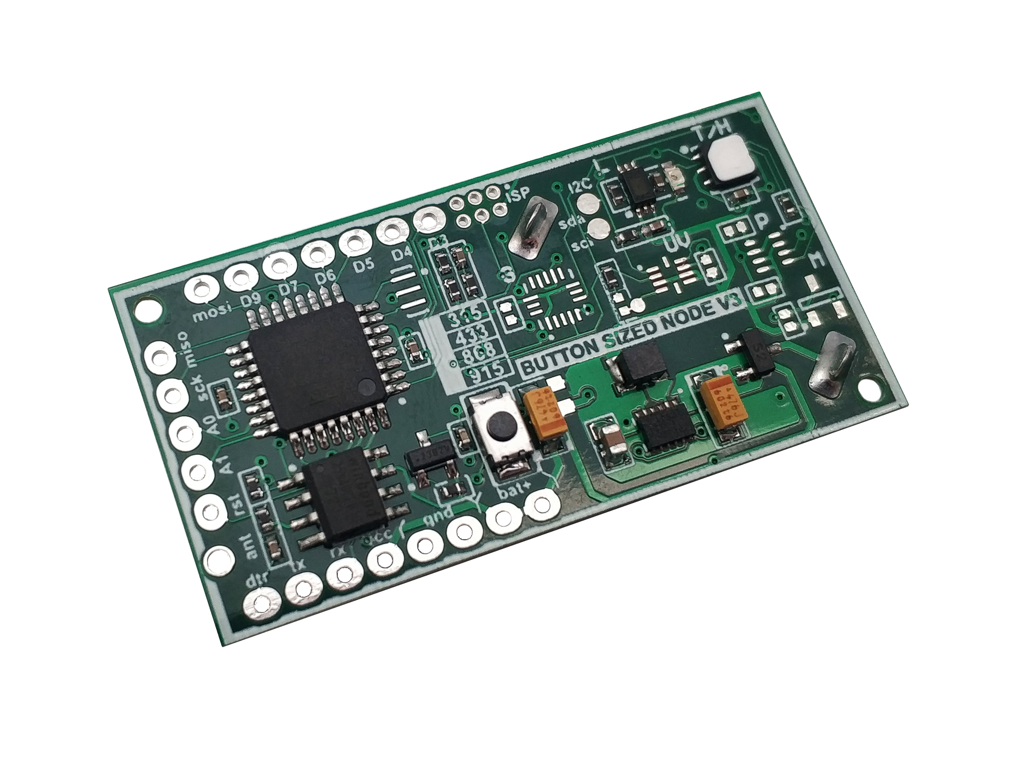


The Button Size Node 3 is a low cost wireless Arduino IDE compatible (the Atmel ATMega328P 8MHz) microcontroller with LoRa RFM 95 or RFM 69 HW(CW) radio on board and few other nice additions.
Best sutable for Home Automation, IOT. Could be used as core board for radio controlling any DIY project. You may think of it as Arduino Pro Mini plus all the items in the picture below::

Specification:
- 4 Layers PCB with larger ground plane improving range. 20-40% range increase according to our field tests.
- Dimensions 45mm x 23mm
- Wide operating temperature range. Tested -20 +40 Celsius
- Sleep current consumption 9 - 12 uA
- Temperature and humidity sensor Si7021
- High Accuracy Temperature Sensor ±0.4 °C (max), –10 to 85 °C
- Precision Relative Humidity Sensor ± 3% RH (max), 0–80% RH
- Light sensor BH1750, spectral responsibility is approximately human eye response.
- OTA FLASH (W25X40CLNIG)
- Accelerometer LIS3DH (full version only)
- Barometer BMP280 (full version only)
- Magnet sensor SM351LT (full version only)
- Authentication security - Atmel ATSHA204A Crypto Authentication Chip
- External JDEC EPROM
- Dualoptiboot bootloader. Implements over the air (OTA) firmware update ability
- LoRa RFM 95 or RFM 69-HW (high power version) or CW (low power consumption version) 915, 868 or 433 MHz Radio transceivers
- Battery voltage sensor (via divider)
- Supply voltage 3.5-10 Volts
- The Digital and Analog pins are 3.3 volts
- Powered by two CR2032 batteries in series with high-efficiency power converter (3.5-10V).
- FTDI header for programming
- LED connected to pin 6
- Reset button
Pin out:
| Arduino Pins | Description |
|---|---|
| A0, A1 | Available ARDUINO analog GPIO / DIGITAL GPIO |
| A2 RFM69/95 reset pin | |
| A6 | Connected to Battery voltage sensor (via divider) 3M/470k |
| A4 | Connected to sensors i2c |
| A5 | Connected to sensors i2c |
| A3 | Connected to ATSHA204A |
| D3, D4, D5, D6,D7, D9 | Available ARDUINO digital GPIO |
| D4 | accelerometer interrupt PCINT20 connected |
| D5 | magnetic sensor state\interrupt PCINT21 connected |
| D6 | LED connected |
| D8 | Connected to CS FLASH chip (OTA) M25P40 |
| MISO, MOSI, SCK, RST | Connected to ISP header |
| ANT | RFM69 antenna |
| Vcc and Bat+ | Unregulated power up to 6.5 Volts is connected before DC-DC converter |
| Gnd | Ground |
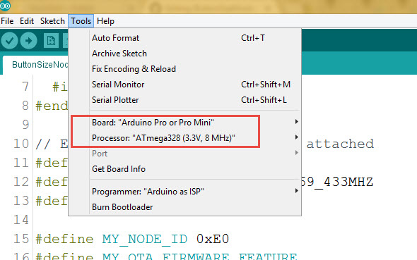
Arduino IDE Settings
programming FTDI adapter connection

Both 3.3V and 5V power options can be used.
How to use it as home automation (IOT) node controller
ButtonSizeNode.ino is the Arduino example sketch using MySensors API.
Connect the Node to FTDI USB adaptor, Select Pro Mini 8MHz board in Arduino IDE and upload the ButtonSizeNode.ino sketch.
Done
The board is created by Koresh


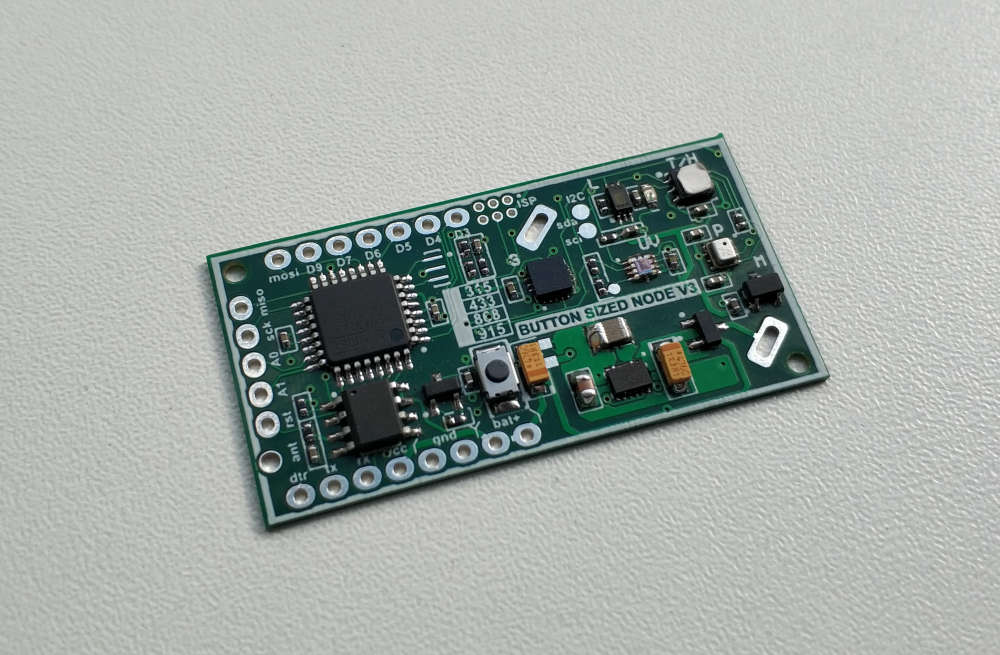
 Button size radionode with sensors swarm extension

