Mysensors RFM69 Livolo 2 channels 1 way EU switch front module
IMPORTANT NOTICE: I will abandon this project because of the bad design regarding the RFM69 module and its antenna - I had not so good results because of that and due to space constraints. I'm switching again to nfr24l01(the NRF51822 RF SOC actually) to see if it performs better in this case. If it works as desired then I'll publish the new project on openhardware.io. Thanks for understanding.
Please bear in mind that I'm not responsible if the Livolo manufacturer will change the board hardware revision on which this project relies!!! This project works with this Livolo board hw revision only: VL-C700X-1 Ver: B8
Description:
This is a Mysensors replica of the Livolo EU Switch(2 channels 1 way) front plate.
Key Features:
- Capacitive touch sensing using TTP223 specialized IC
- AT25DF512C-SSHN-B SPI flash module for OTA
- ATSHA204A for signing
- MySensors ready(Atmega328p + RFM69CW)
- DC-DC Buck converter in combination with a linear LDO voltage regulator for efficient noise cancelling (the used LDO reduces a little bit the Buck's converter current capability - down to 150mA from 600mA but this is not important as the whole board takes about 60mA at peak)
Work progress:
- Identify the 12V line from the Livolo power/relays board - DONE
- Add AT25DF512C-SSHN-B SPI Flash module for OTA and ATSHA204A for signing - DONE
- Test/verify the pcb board correctness(from both electrical and mechanical point of views) - DONE
- Produce the initial PCB's using some external PCB manufacturer - DONE
- Components assembly(soldering) - DONE
- Create Mysensors sketch code - DONE
- Verify the real board with running code - DONE
- Verify OTA - DONE
Regarding point 1. from above: the EU variant that I have(VL-C700X-1 Ver: B8) doesn't expose the 12V line unfortunately. So I see 2 options here:
- Bypass the 3V regulator from the power supply/relays board completely so that I get 12V directly to my board
Find a free(if available) pin on the 2x6 pin connector and solder a wire to that pin from the 12V line(this requires less intervention)
One another thing that I noticed is that the relays are bistable so I modified the schematic/pcb to accommodate that(the relays used on my livolo switch are: HFE60 12-1HST-L2 - 2 coils latching, 1 Form A as per datasheet).
Instructions:
This Livolo switch needs to be bought first(VL-C702 series)
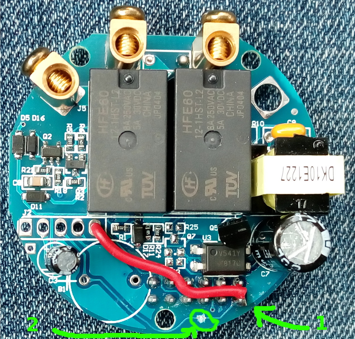
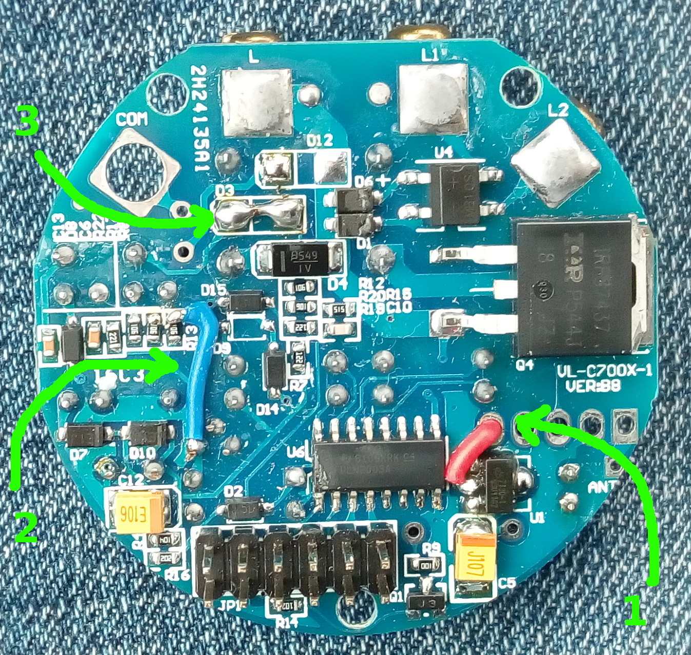
Power/relays board needs some modifications as seen down below:
a) green marking no. 1 represents the 12-14V line wire connected to the power connector
b) green marking no. 2 represents the old 3V line trace cut from the power connector

a) green marking no. 1 represents the 12-14V line wire connected to the power connector
b) green marking no. 2 represents the modification needed for the resistor divider that drives the MOSFET
c) green marking no. 3 represents the big resistor(marked as 104) removed and replaced with a solder bridge

Need to adjust touch sensor capacitors for touch sensitivity if needed(caps marked with 0-50pF* on the board) - *I used 2pf capacitors**
Need to adjust LEDs series resistors regarding brightness(resistors marked with 1K* on the board) - *I used 5K1 resistors**
Burn MCU fuses using avrdude like this:
avrdude -cusbasp -pm328p -U lfuse:w:0xe2:m -U hfuse:w:0xda:m(for internal 8MHz RC oscillator and bootloader)Burn DualOptiboot bootloader
Upload the provided sketch with this project or roll your own(pay attention to set this preprocessor define:
#define MY_OTA_FIRMWARE_FEATURE)The provided sketch accepts on V_VAR1 this message format(with a limit of 25 characters) < node_name >:< sensor1_name >:< sensor2_name > - what this does is it will store those values in EEPROM and assign them to the node. Basically you get a node with named sensors instead of just displaying the numeric ids.
Very important:
- A capacitor is also needed in parallel with the light bulb otherwise the project board won't work as it doesn't get enough power from the standby circuit. I used a 470nF X2 type rated at 310Vac. I recommend using a light bulb of 10W or more(in my tests I used a 15W one.) I tested the setup with a 5W LED bulb but I got some instability from the livolo power supply board(it started to oscillate) - in this case maybe a bigger capacitor across the bulb might help(1uF one maybe). You don't need 2 capacitors in case of the 2 ways switch for each light bulb - one is sufficient across one of the bulbs.
Oh and please don't touch directly with your finger the sensor plates - use the plastics from the original board. I'm not responsible if you get an electric shock. 2. I noticed that the board is more stable if using good tantalum capacitors in the last power stage(on MIC5205 output) and for the radio module(10uf is enough - R type or 0805 metric which work on the 0603 hand soldering footprint too as it has longer pads - tested this myself) 3. As the space available is pretty limited a Helical antenna design can be used
HW Revisions:
- 0.1 - added SPI flash for OTA and signing support
- 0.2 - fixed SPI slave select lines for flash and radio module
- 0.3 - added ATSHA204A pull-up resistor
- 0.4 - fixed leds orientation and added touch pads silkscreen
- 0.5 - added tantalum caps for better power supply and radio stability(removed MCU reset pin cap)
Credits:
All credits go to MySensors team for the great work and to the opensource community
