@Andrew-Currie Downloaded KiCad and used it to import jBoard2.brd and output .gbr files via Plots plus the .drl file. Checked using GerbView and uploaded to PCBWay. Hopefully this will now work...
jModule2
License:
Attribution-ShareAlike (CC-BY-SA)
Created:
8 years ago
Updated:
8 years ago
Views:
213404
22 Like
8 Collect
10 Comments
356 Download (625.7 kB)
jModule2
Extension module with Arduino Pro Mini connected with nRF24L01 radio.
The goal of this project is to create a module for further use with "mySensors". The module must be as small as possible, easy to build and cheap.
Build instruction
Prepare elements:
- jBoard2
- Arduino Pro Mini compatible board
- nRF24L01 radio
- LE33 voltage regulator
- 4,7uF capacitor
- 1x4 angular female header
- 1x4 extended pin header
- 1x8, 1x2 angular pin headers

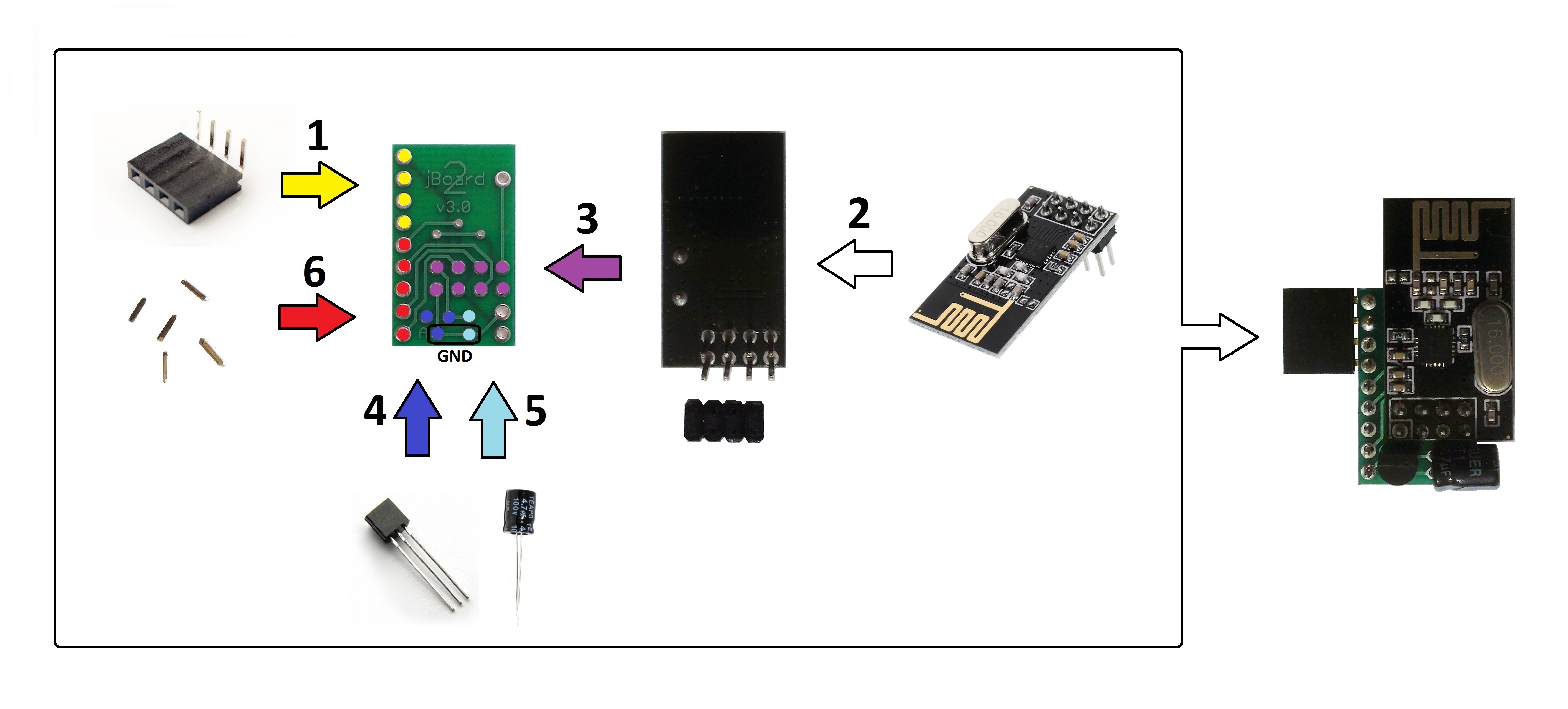
- Solder 1x4 angular female header to jBoard2. Solder it from the top side of the board.
- Cut off nRF24l01 radio pins - leave them 0.8mm long (the jBoard2 thickness). Keep 5 of the cut-of pins - they will be used for step 6.
- Solder the radio to jBoard2. The 1x4 angular female header from step 1 should be between the jBoard2 and the radio.
- Solder LE33 voltage regulator to jBoard2. Cut off protruding pins as close to the board as possible and smooth the pins. If you use 3v Arduino Pro Mini skip this step. Instead of this make a connection between Vin and Vout pads for the regulator on the jBoard2.
- Solder 4,7uF capacitor to jBoard2. Cut off only VCC protruding pin as close to the board as possible and smooth the pin. Do not cut off GND pin!
- Solder the cut-of pins from step 2 to jBoard2. Solder them from the top side of the board.

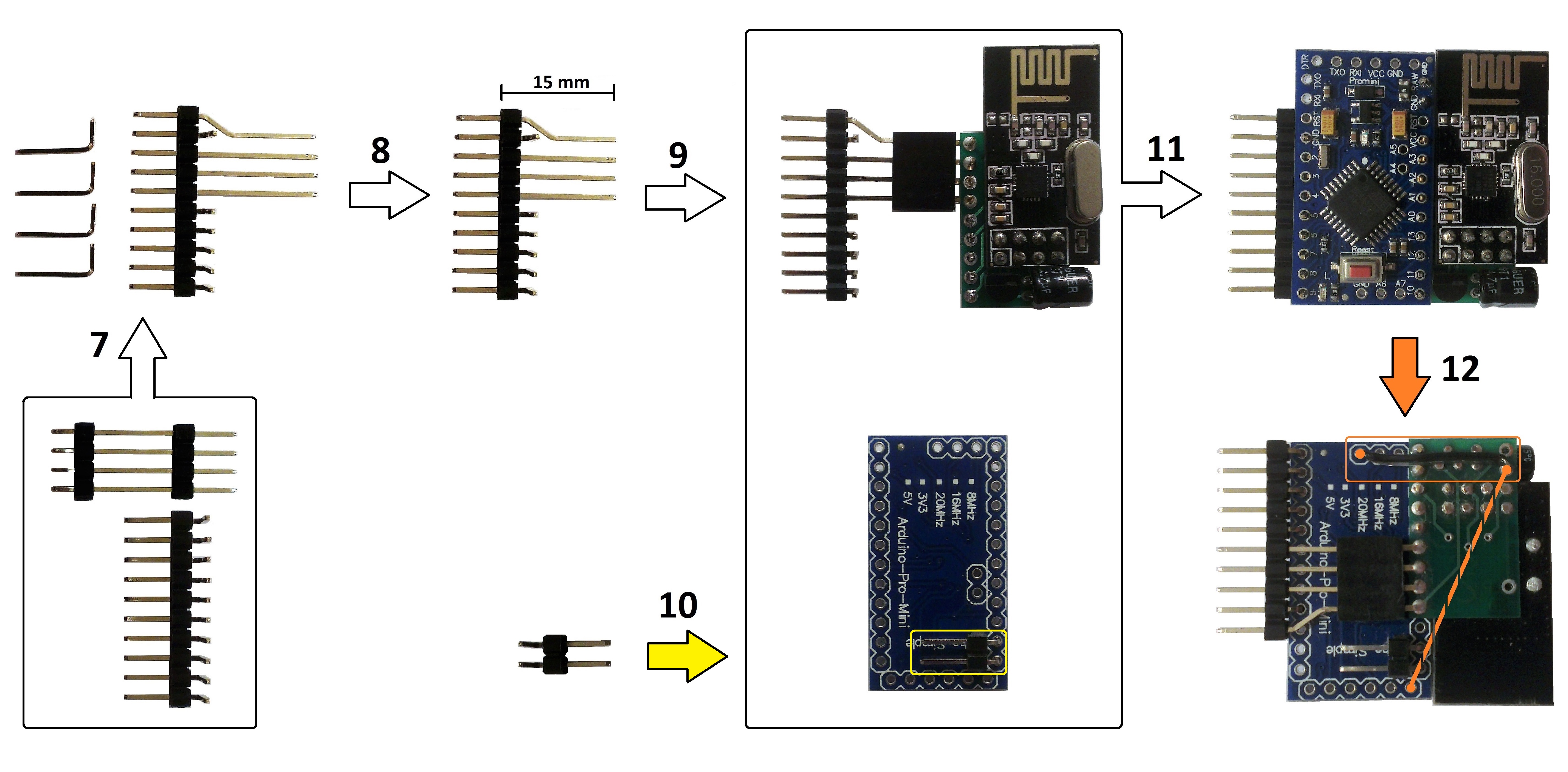
- Replace 4 angular pins with the extended ones. If you do not need analogue outputs replace only the first angular pin. Next bend the fist replaced pin - see picture above.
- Cut off extended pin/s, leave them 15mm long - see picture above.
- Plug in the connector to the 1x4 female header.
- Using an adhesive tape make an electrical insulation. Secure all Arduino Pro Mini pads which could connect to jBoard2 pads.
- Solder 1x2 angular pin header to Arduino Pro Mini.
- Combine Arduino Pro Mini with the jBoard2 and solder them. When you finish cut off a capacitor GND pin.

Done :). The module is ready to talk with your "sensor projects".
- 8 IO pins(A1...A3, 5...9) plus one GND pin and one VCC pin are located on one side.
- Only a 1x8 female header on the edge of your board and 2 wires from a power supply are needed to use the module.
- Easy to access serial interface for programming.
Important note

Alternative build option

- Solder 1x4 angular female header to jBoard2. Solder it from the bottom side of the board, it should stick out the board.
- Remove a plastic distance from nRF24L01 radio.
- Solder the radio to jBoard2. Cut off nRF24l01 radio pins and smooth the pins. Keep 5 of the cut-of pins - they will be used for step 6.
- Solder LE33 voltage regulator to jBoard2. Cut off protruding pins and smooth the pins. If you use 3v Arduino Pro Mini skip this step. Instead of this make a connection between Vin and Vout pads for the regulator on the jBoard2.
- Solder 4,7uF capacitor to jBoard2. Cut off protruding pins and smooth the pins.
- Solder the cut-of pins from step 2 to jBoard2. Solder them from the bottom side of the board.

- Replace 4 angular pins with the extended ones. If you do not need analogue outputs replace only the first angular pin. Next bend the fist replaced pin - see picture above.
- Cut off extended pin/s, leave them 15mm long - see picture above.
- Plug in the connector to the 1x4 female header.
- Solder 1x2 angular pin header to Arduino Pro Mini.
- Combine Arduino Pro Mini with the jBoard2 and solder them.
- Using a wire connect GND pads. The dotted line - if your Arduino Pro Mini does not have an extra GND pad.

Done :). The module is ready to talk with your "sensor projects".
- 8 IO pins(A1...A3, 5...9) plus one GND pin and one VCC pin are located on one side.
- Only a 1x8 female header on the edge of your board and 2 wires from a power supply are needed to use the module.
- Easy to access serial interface for programming.
