@Roland-Wijnen Hi! Were you able to compile the available files? I tried, but there has been a lot of error!
Yo! This project is still a Work In Progress. Instructions, board layouts and BOM might change!
MySensors ESP8266 MQTT gateway
License:
MIT
Created:
8 years ago
Updated:
8 years ago
Views:
16514
12 Like
11 Collect
6 Comments
1088 Download (5.99 MB)
This project is a Mysensors gateway using the full capabilities of the ESP8266.
Features:
- Configuration through a web interface. When there is no configuration found in flash, the ESP8266 flash button is pressed for more than 10 seconds, or using the web interface, the Wifi and MQTT configuration can be set using a web page.
- Access point mode when Wifi configuration is not valid.
- Sensor status is displayed on a web page, this helps out when debugging your sensor network.
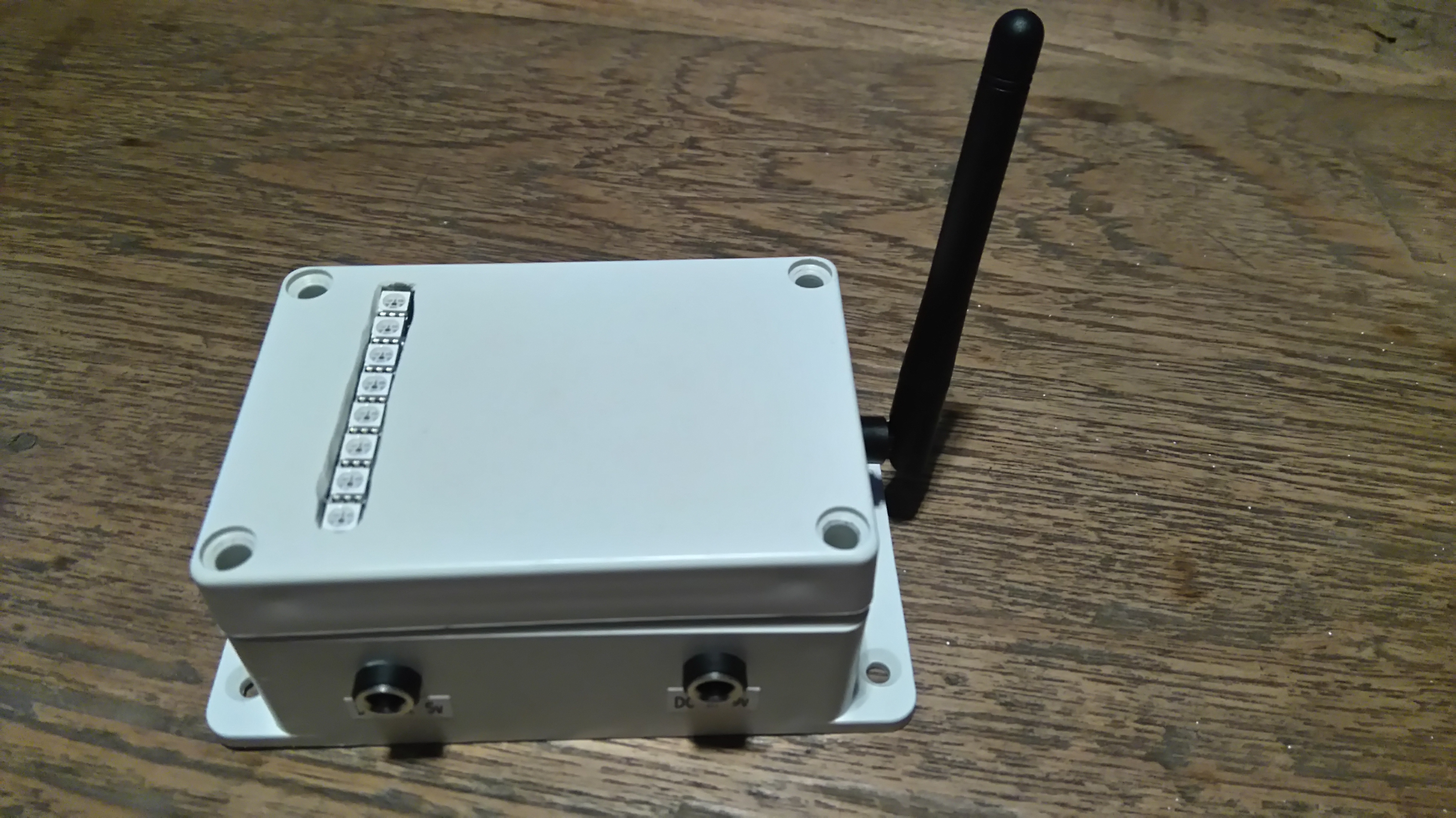
- Gateway status is presented in 8 RGB leds using a neopixel stick:
- Mode: Application, or Access point mode.
- Wifi connection
- Wifi signal strength
- Led transport error indication
- MQTT: Shows connection status, and when data is sent or received
- Sensor Network data received
- Sensor network data sent
- One spare ;-)
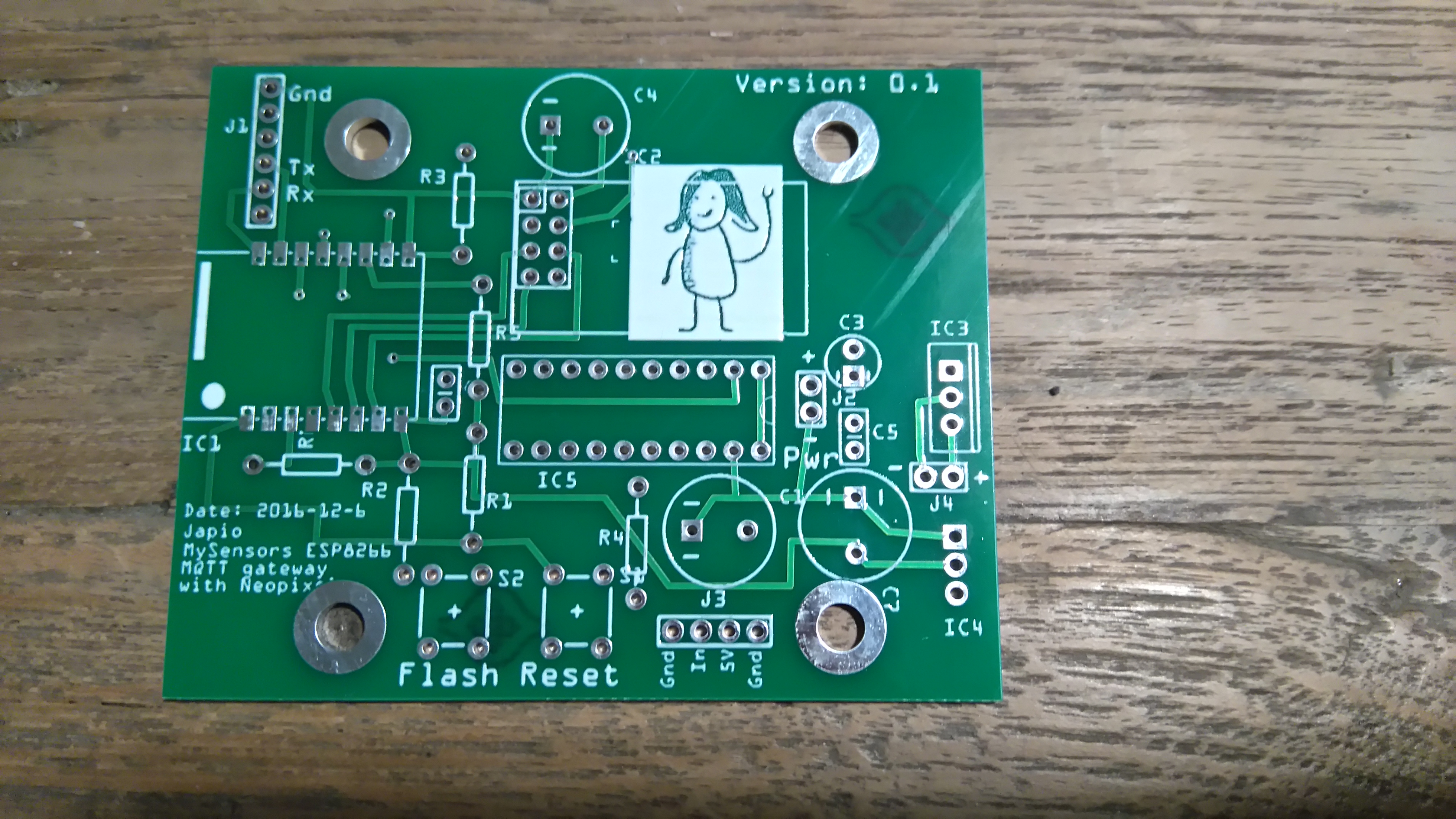
- PCB is designed such that it nicely fits into a standard 100 * 68 * 50 mm enclosure.
- Additional 5 volts DC out for slave sensors.
Build instructions
Build
(Assuming your collected all the parts, and the board itself)
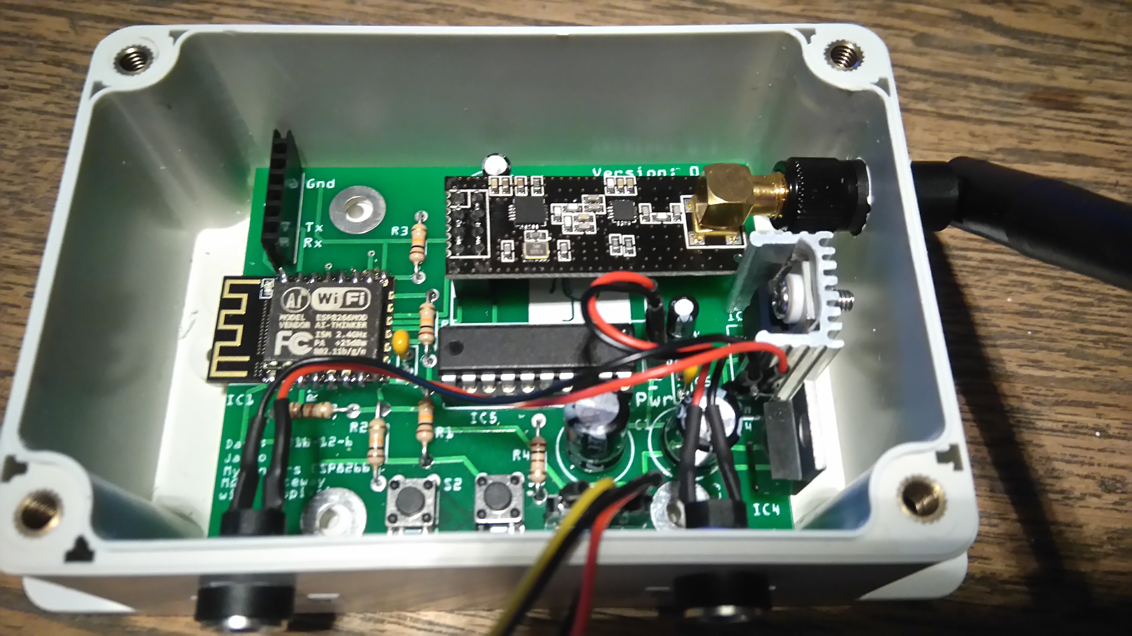
- Solder all the parts, starting with the ESP8266. This is the lowest part.
- When all parts are soldered, power the board using a 9 volts power adapter.
- Connect a FTDI Serial to USB converter to J1 (You can solder a female header here, and plug the FTDI in here.
- Connect a Neopixel stick to J3
- Download the program using the Arduino IDE (Press and hold Reset, press and hold Flash, release reset, after some seconds release Flash buttons. This puts the ESP into programming mode.
Configuration
Now you are ready to do final configuration:
- Connect to the MySGateway Wifi network, and point your web browser to go to 192.168.4.1.
- Press the "Configuration" link. In the page that shows enter your wifi configuration and MQTT broker settings.
- When you click the "Save" button, configuration will be saved in flash, and the gateway will reset.
- After reset, the Mode led should go green, Wifi Connection led should turn green, and the MQTT led should go green as well.
Mounting
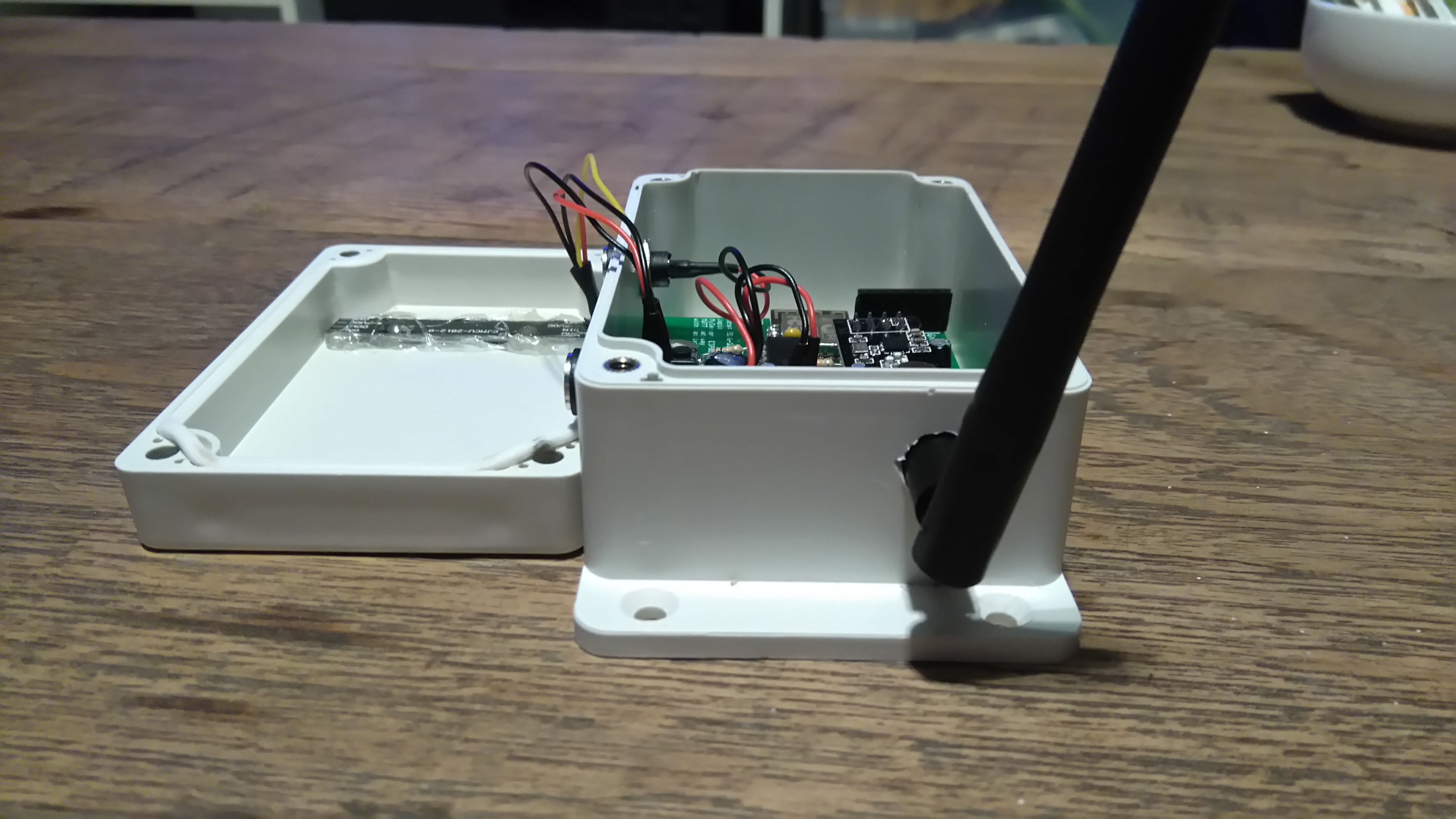
The PCB is designed such that it fits nicely in the following enclosure: Enclosure
Drill holes for the DC connectors and if you use the NRF with the external antenna, a hole for the antenna as well.
Connect the slave sensor power to J4
Connect the input power connector to J2
Cut a hole in the enclosures cover to accommodate the Neopixel stick. I glued the stick to the enclosure with some hot-melt glue
Connect the stick to the PCB J3
Now you are done!


