The purpose of this project is to replace the thermostats of my
electric radiators in my house.
The heating system of my house is a typical 1970s installation
in Sweden, electric radiators with built-in bimetal thermostats.
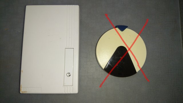
A couple of years ago I bought a product called IQTherm for upgrading
the thermostat function. In each room you install a module with a
triac (TR/P) that pulses the current to each radiator to get 0-100%
power. In each room the triac module is controlled by a thermostat
module (EL) which can be programmed with a (IR) remote control from a short distance.

When I recently stumbled upon MySensors I got the idea of controlling
the heating with home automation. So I started to implement a MySensors
node that could connect to the triac module and do what the thermostat
module does. But now I will be able to control the heating from
Domoticz, or any other HA controller.
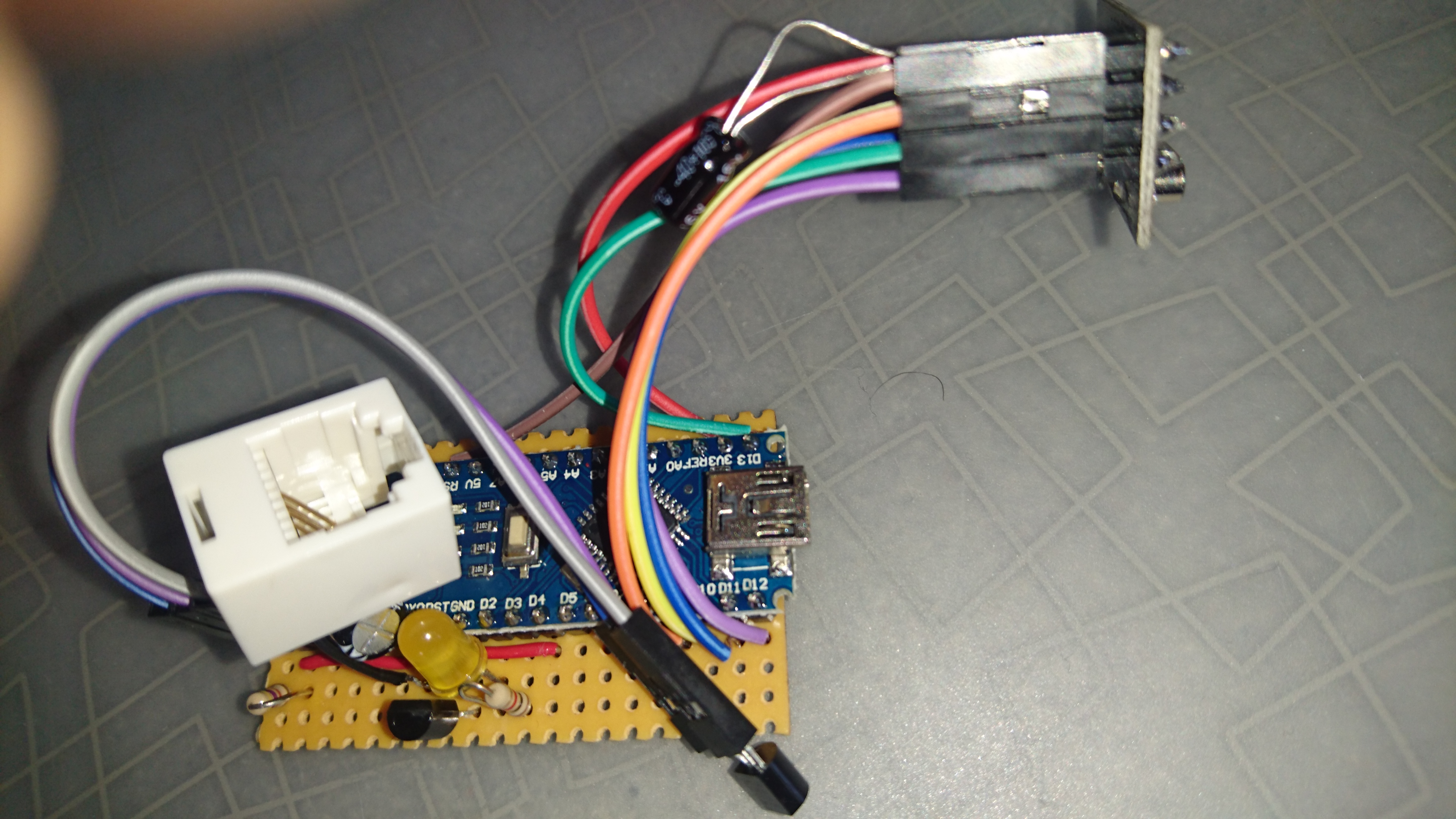
The MyQTherm sensor node is connected to the triac module with a cable with
4 leads. 2 of the leads carries 12V AC from triac module to the sensor
node for power. The other 2 leads has 12V DC signal from sensor node
to triac module, enabling/disabling the power to the radiator.
The sensor node measures the room temperature with a DS18B20 also
connected through a 4 lead cable. Optionally you can attach a mini PIR
motion sensor to this cable so the node can detect presence in the
room. The 4 pins are +5V, GND, PIR, TEMP. TEMP is connected to D4 on the
Arduino, PIR is connected to D5. The PIR pin could equally well be
connected to a reed switch to operate as door alarm.
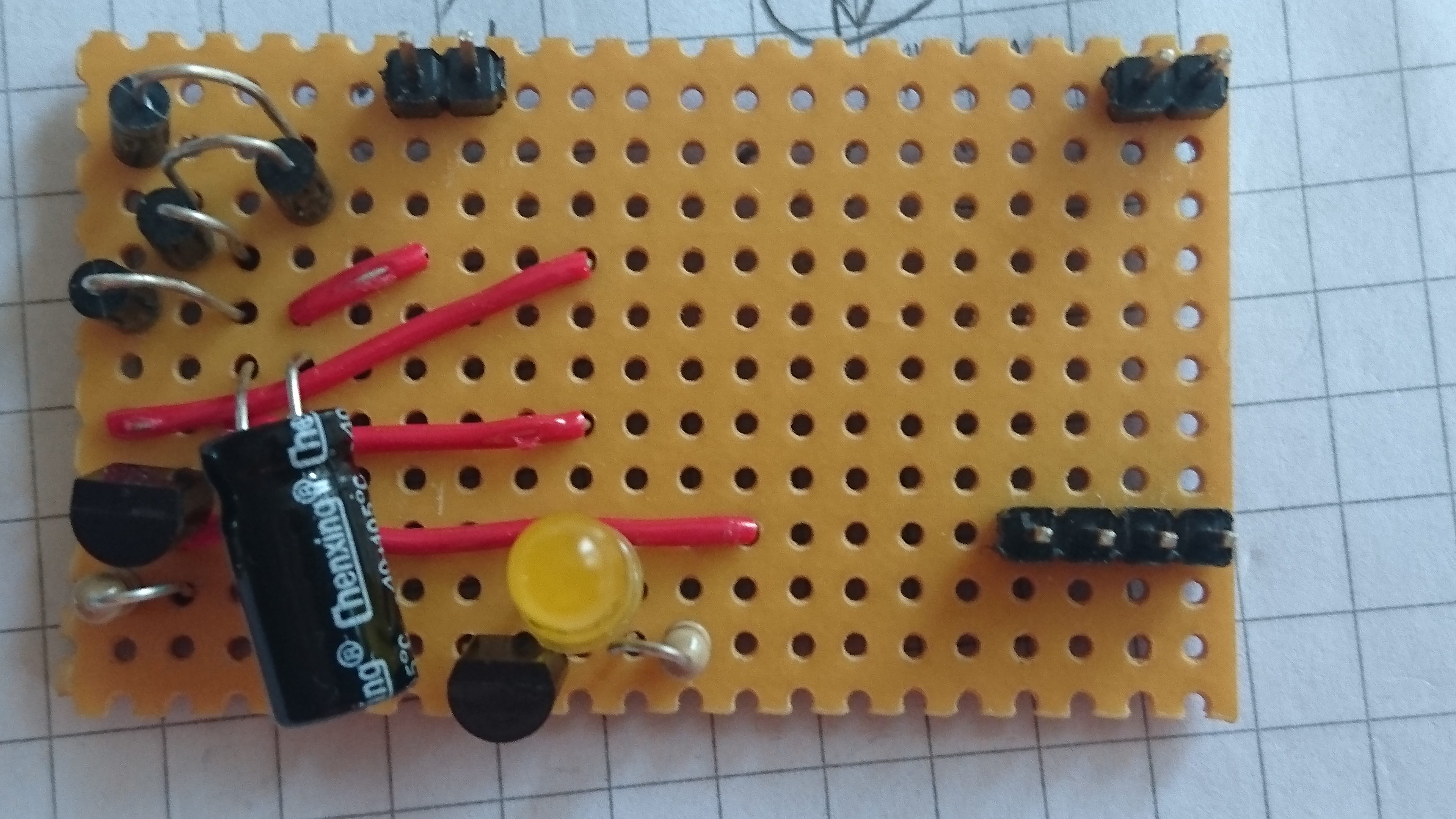
So far I have built a prototype on stripboard using a Arduino nano for
convenience. I am currently designing a PCB where I will use a 5V
Arduino pro mini (clone). This is the very first PCB I have worked
with so it might not be so pretty.


First I was thinking of putting the sensor node inside the triac
module. But I ruled it out since there is 400V in there and not enough
space.
I also put the temperature sensor inside the sensor node at
first. Then I dicided to have it at the end of a thin cable for easier
placement a small distance from the radiator.
As controller I started out with Domoticz so I know that the sketch
works pretty well with that. I cannot guarantee that the sketch works
equally well with any other HA controller.
The sketch is still in beta phase with some debugging info printed.
The sensor node regularly sends data to the controller: current
temperature, current power output to radiator, energy consumption and
tripped state of optional motion sensor.
My plan is now to finish the PCB and send it to itead or seeed for
production. For casing I will probably use a bit of a cable duct. This
will be attached to the side of the triac module.
So I would very much like to have some feed back on the board design and the sketch.
Update: I have received the PCBs and built a node which I am testing live
in a room in my house. It is working smoothly!
In my sketch I have implemented a simple PID algorithm to control the output power.
 MyQTherm - replace IQTherm heating thermostat:
 , just to get something working. You have to keep your interest in HA alive in the meantime. But the reward is great when you get MySensors working.

