I think you can just set the I2C pins in MyBoardNRF5.h without remapping the pins in MyBoardNRF5.cpp.
Look in MyBoardNRF5.h, under the Wire Interfaces section. Set SDL and SCA to 30 and 31 as appropriate for your board.
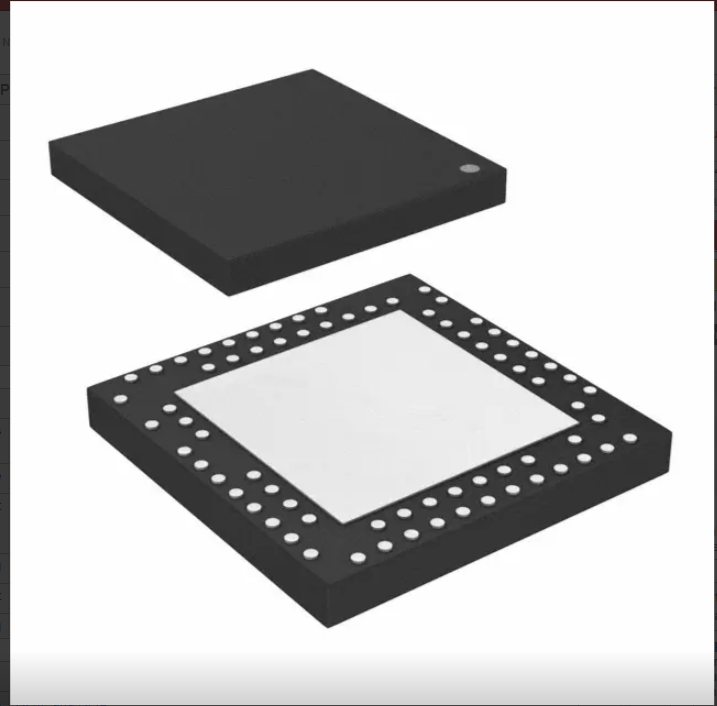
The NRF24L01+ chip is used in many MySensors projects. This chip depends on an additional processor like an ATMEGA. With Nordic Semiconductor NRF5 series a powerful alternative as combination of CPU and Radio is available.
The NRF5 chips have an on-chip radio module which is compatible with the NRF24 series or BLE. At the current state, BLE is not supported by MySensors. The NRF5 series has a lot of internal Hardware:
- ARM Cortex-M0 (NRF51)/Cortex-M4 with FPU (NRF52)
- 16k-256k RAM
- 128k-1M Flash
- 31 GPIO ports
- ADC
- Timers + RTC
- Hardware Number Generator
- Internal temperature sensor
- SPI
- I2C
- UART
- Watchdog timer
- Comparator and Low Power Comparator
- PWM
- AES (encryption, CCM for encryption, ECB for hashing)
- USB (nRF52840)
- ...
With Shortcuts and the PPI (Programmable peripheral interconnect), the periphery can do a lot, work without CPU interaction like enable or disable radio on a timer event.
Using the MySensors board definition, you can manage the pin definition as part of your Arduino Sketch. This allows you to design your sensors node (mostly) without caring about where SPI, I2C, UART pins have to connect to. Some pins like ADC or NFC are restricted...
Buying guide
At the moment three different series of boards available. The nRF51 series including the nRF51822 (BLE license) and nRF51422 (BLE & ANT+ license) and the nRF52 including the nRF52832 and nRF52810 and the nRF52840 series. Currently, the nRF52832 and nRF51822 are supported so we recommend sticking with those for now. If you're not sure which one to choose, get the nRF52832. It is faster, consumes less power and the chip is more flexible.
There are a lot of hardware modules available with these chips. For standard MySensors nodes we recommend choosing a version with the high-frequency oscillator attached which is included in most modules available. If you plan to make a battery powered sensor, you should choose a module including the low-frequency oscillator (32,768kHz) for precise low power sleep modes and the inductor the for DC/DC regulator.
Required Hardware and Drivers
Most nRF5 modules comes without programmer and serial converter. You need to buy a dedicated programmer (CMSIS-DAP/DAPLink 1.5, J-Link or ST-Link v2) and mostly a 3.3V USB to serial converter (J-Link and ST-Link). With Linux most programmers and serial adapters are supported. With Windows, you have to look if a signed driver is available for your programmer and serial device.
A proven variant to start program various devices without dealing with a lot of drivers or bad hardware is to buy a RedBear BLE Nano2 kit.
Linux
With Linux, you can use any type of supported programming adapter (J-Link, ST-Link v2 and DAPLink). For fixing the permissions a file "/etc/udev/rules.d/50-programmer.rules" is required. You have to add your user to the "plugdev" group.
# CMSIS-DAP
ATTRS{idVendor}=="0d28", ATTRS{idProduct}=="0204", MODE="664", GROUP="plugdev"
KERNEL=="hidraw*", ATTRS{idVendor}=="0d28", ATTRS{idProduct}=="0204", MODE="664", GROUP="plugdev"

# J-Link
ATTRS{idVendor}=="1366", ATTRS{idProduct}=="0101", MODE="664", GROUP="plugdev"
ATTRS{idVendor}=="1366", ATTRS{idProduct}=="0105", MODE="664", GROUP="plugdev"

# ST-Link
ATTRS{idVendor}=="0483", ATTRS{idProduct}=="3748", MODE="664", GROUP="plugdev"
Windows
For windows, you need to install the correct driver. A good starting point is to use Zadig which installs a lot of drivers. When it's not working you can install the correct driver manually:
- CMSIS-DAP: Driver Setup for mbed devices
- J-Link: Zadig
- ST-Link: ST-LINK, ST-LINK/V2, ST-LINK/V2-1 USB driver signed for Windows7, Windows8, Windows10
If you have trouble with J-Link adapters, install the original Software (J-Link Software and Documentation pack for Windows](https://www.segger.com/downloads/jlink)), start "J-Link Configurator" for firmware updates and remove all software and drivers and restart zadig to install WinUSB.
OSX
"No additional setup required." Look at https://github.com/sandeepmistry/arduino-nRF5/#os-x
Preparing Arduino
Arduino supports the nRF5 platform in a standard setup. You have to add the arduino-nRF5 platform via Arduino's Board Manager as described in https://github.com/sandeepmistry/arduino-nRF5/#installing
You have to choose "None" in the "SoftDevice" menu.
You can use your own pin definition with the MySensors board definition.
The Arduino port for nRF52 MCUs provided for Arduino Primo Boards is not compatible with MySensors at the moment. The reason is the existence of the SoftDevice handling BLE connections. MySensors can be compiled for the Primo board, but the NVM driver is incompatible. When Arduino Primo has an option to disable the SoftDevice, then MySensors can be used with the Arduino Primo variant. You can use the Arduino Primo variants with a custom board definition with the MySensors board definition.
Preparing the MCU
The MCU requires a complete erase. You can use this Sketch to erase the MCU. The BLE functionality is not available after erasing the MCU. Note: this Sketch produces no output.
#include <nrf.h>
void setup() {
  // Enable erasing flash
  NRF_NVMC->CONFIG = NVMC_CONFIG_WEN_Een << NVMC_CONFIG_WEN_Pos;
  while (NRF_NVMC->READY == NVMC_READY_READY_Busy) {
  };
  // Erase Flash and UICR
  NRF_NVMC->ERASEALL = 1;
}
void loop () {
}
Configure MySensors
Starting with MySensors 2.2.0 release, the nRF5 platform is supported.
There is no need to configure anything special to create a MySensors Node or Gateway. Add a "#define MY_RADIO_NRF5_ESB" to your sketch to enable the radio device in Enhanced ShockBurst mode (ESB). This mode is compatible with MySensors nRF24 implementation.
Migrate code
EEPROM like memory
The nRF5 MCU has no EEPROM memory like AVR controllers. The internal flash can erased 10,000 (nRF52) or 20,000 (nRF51) times per page. To extend the lifetime there is a NVRAM class. By using hwReadConfigBlock, hwWriteConfigBlock, hwReadConfig or hwWriteConfig the memory can be accessed.
Any write operation is added to an internal log. This operation is fast until the log is full. When the log is full, a new flash page from an internal pool is written. This process can take up to 4 seconds. If you need to write often in a time critical situation, call the MySensors "sleep" function with a time > 5000ms. This forces to clear the log when its not possible to write more than 32 bytes.
The number of available writes per byte depending on the highest address written in NVRAM. When you only use the first 8 bytes of the NVRAM, you have 5,100,000 write cycles per byte. If you use all 3072 bytes available, you have only 3,300 write cycles per byte.
GPIO Input mode
Many of MySensors examples configure input with a pullup resistor by writing high to the input pin. This doesn't work with the nRF5 chips. Here is an example:
// Incorrect
// pinMode(BUTTON_PIN,INPUT); // Setup the button
// digitalWrite(BUTTON_PIN,HIGH);   // Activate internal pull-up

// Correct
hwPinMode(DIGITAL_INPUT_SENSOR, INPUT_PULLUP);
GPIO Output mode
If you configure a pin as OUTPUT pin with pinMode command, the pin can drive a current of 2mA without violating the specification. If you want to use more current, you have to switch to the "High Drive" mode. Please read the GPIO documentation at https://infocenter.nordicsemi.com
At the moment in Arduino, there is no definition of various OUTPUT modes. If you want to access all nRF5 output modes, you have to use hwPinMode and the OUTPUT_... macro. The modes available are:
- OUTPUT_S0S1 -> Standard 0, Standard 1
- OUTPUT_H0S1 -> High Drive 0, Standard 1
- OUTPUT_S0H1 -> Standard 0, High Drive 1
- OUTPUT_H0H1 -> High Drive both
- OUTPUT_D0S1 -> Disconnected 0, Standard 1
- OUTPUT_D0H1 -> Disconnected 0, High Drive 1
- OUTPUT_S0D1 -> Standard 0, Disconnected 1
- OUTPUT_H0D1 -> High Drive 0, Disconnected 1
Interrupts
If you create your own interrupt routines, please use the NRF_RESET_EVENT macro to reset an event. This macro incorporates with the caching of NRF52 MCUs.
NRF_RESET_EVENT(NRF_RADIO->EVENTS_END);Watchdog timer
The MySensors port for nRF5 supports using the Watchdog. You can use the same commands like defined in "avr/wdt.h" but disable cannot disable the watchdog. The watchdog is set to a period of 36h of CPU runtime.
When the CPU is in a sleep mode, the watchdog timer is stopped.
Don't set the watchdog timeout below 4500ms, this can conflict with the usage of the NVRAM (EEPROM like memory)
Known Issues
While sleeping and waiting for a pin change, the current consumption is 1mA on older nRF51 chips. The fix is documented at http://infocenter.nordicsemi.com/pdf/nRF51822-pan_v3.0.pdf


 MySensors NRF5 Platform
