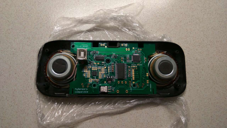
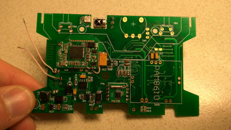
Finally solved a lot of problems and checked a lot of mistakes. But now the first version of this device works almost properly :trollface:
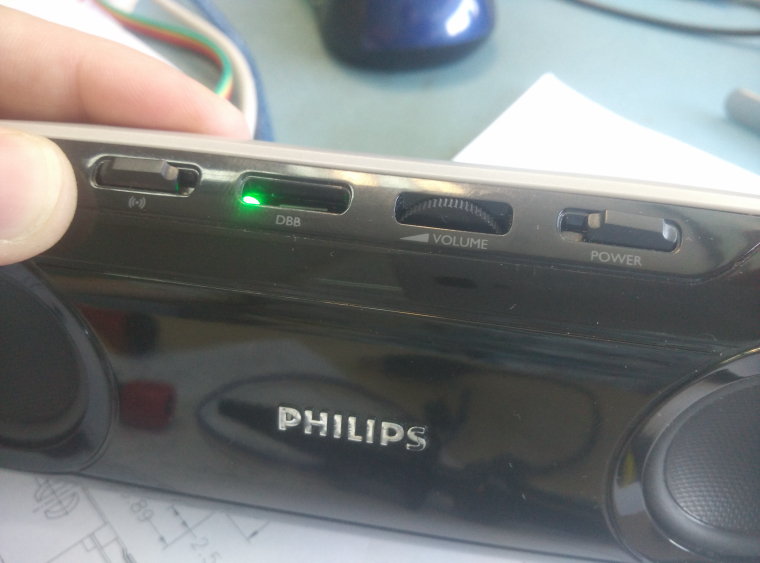
I will make a small report in the description asap 
It is not a MySensors project (in its pure form). But may be somebody finds something interesting.
Many years ago my wife had a nice gadget as a gift. It was Philips SBA290 speakers.
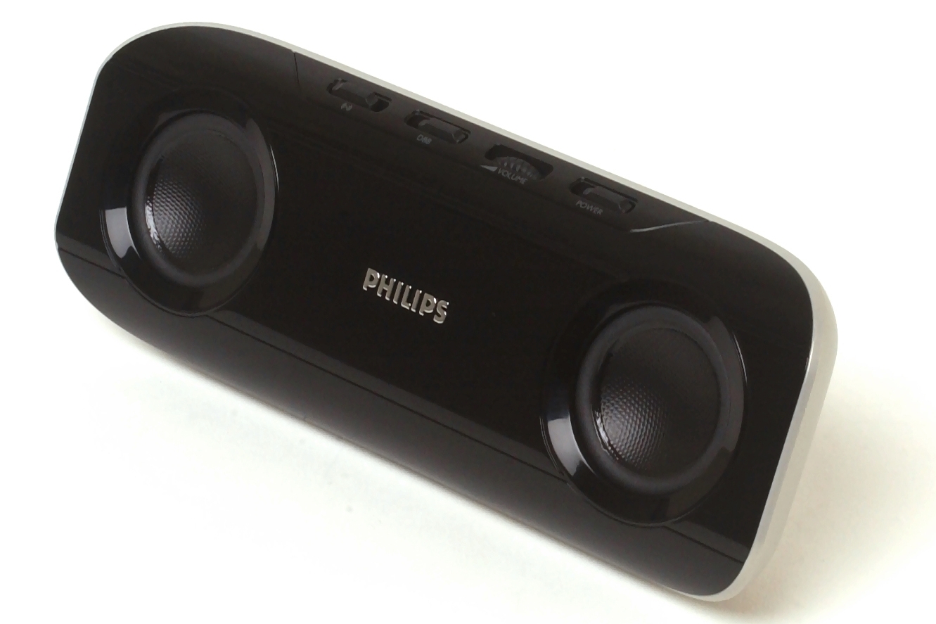 (it is not my photo, because my device is disassembled :))
Some years ago I disassembled it to modify, because it had some serious drawbacks I thought. First, it requires SIX (!) batteries (AAA). Moreover if you try to use rechargable batteries, the device can't charge them and you must do it yourself. Second, it has an antiquated 9V transformer power supply (~500g weight) with a non standard plug. And third, it is depreciated because it has no modern connectivity interfaces like bluetooth. So it is very beautiful with very nice speakers but it's use is not practical.
So I disassembled the device with great plans and... it just lies neglected some years because I have no time to start and finish this small project. :)
But some days ago we suddenly found it and my wife asked my to turn it on ))) So I had some holidays, a disassembled device and many ideas.
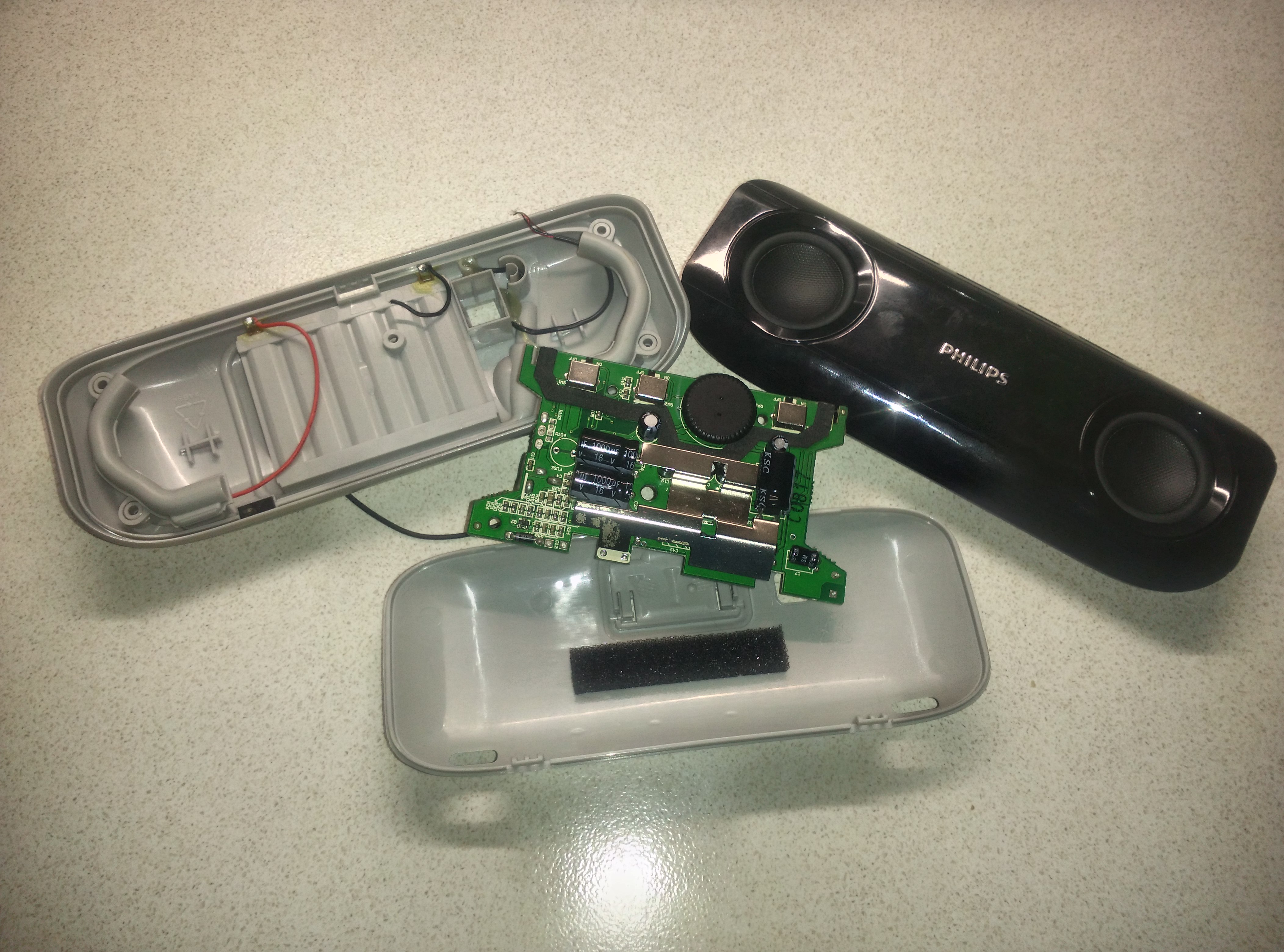
At first I decided to not decrease device functionality. So after modification it must have all old functions. Just a list of them all:
- You can connect audio source via 3.5mm cable.
- You can power device using external power supply (WOW )))
- Device has analog audio processor (sound effects buttons).
- Device looks good.
First two points are trivial and I will accomplish them, no doubts. The third point... a little difficult, because I am absolutely sure I do not want to realize an analog equalizer but I have some experience with digital audio processors so it looks realistic. The last point is the main challenge. So we can't use screens or other extreme upgrades because it will look... you understand :)
Now I will try to list desirable functions in order of priority:
- Device must have rechargeable battery and charge\discharge controller with battery protection.
- Device must have audio processor.
- Device must have AUX input.
- Device must have standard and convenient power supply plug.
- It must have hardware volume wheel and buttons.
- Device must have relatively high power amplifier.
- Device should have bluetooth connection ability.
- It seems device will have microcontroller so it would be fine to have alility to program it via USB without disassemble.
- Device should have FM-radio.
- It would be perfect to have remote control.
- MySensors compatible... why not!
Oh... And all it must be fitted on the board with suitable shape.
After some thoughts I drew the preferred BLOCK DIAGRAM of the device:
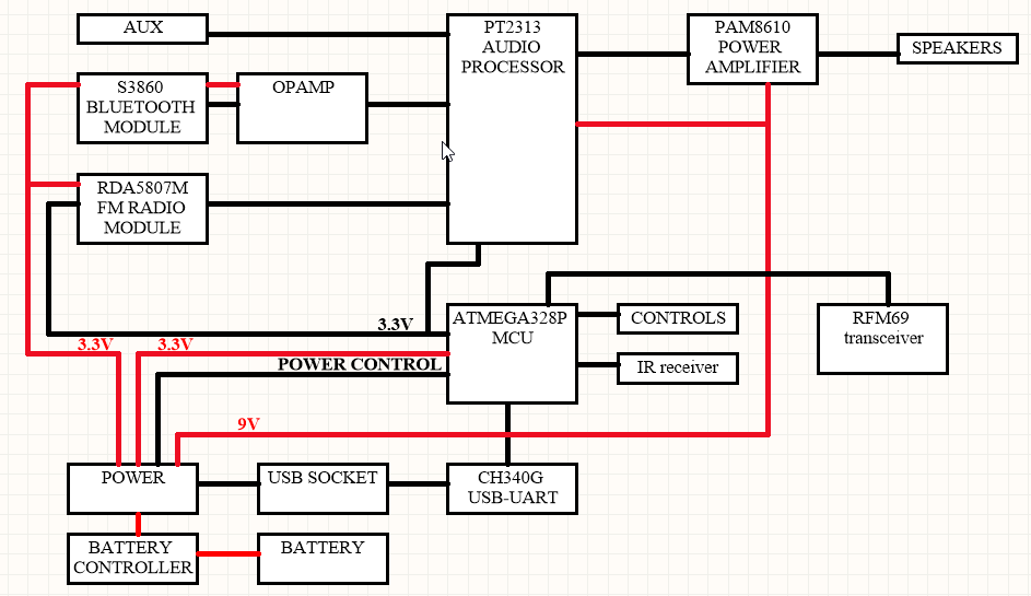
I tried to use parts which I have so I am not sure my construction is optimal.
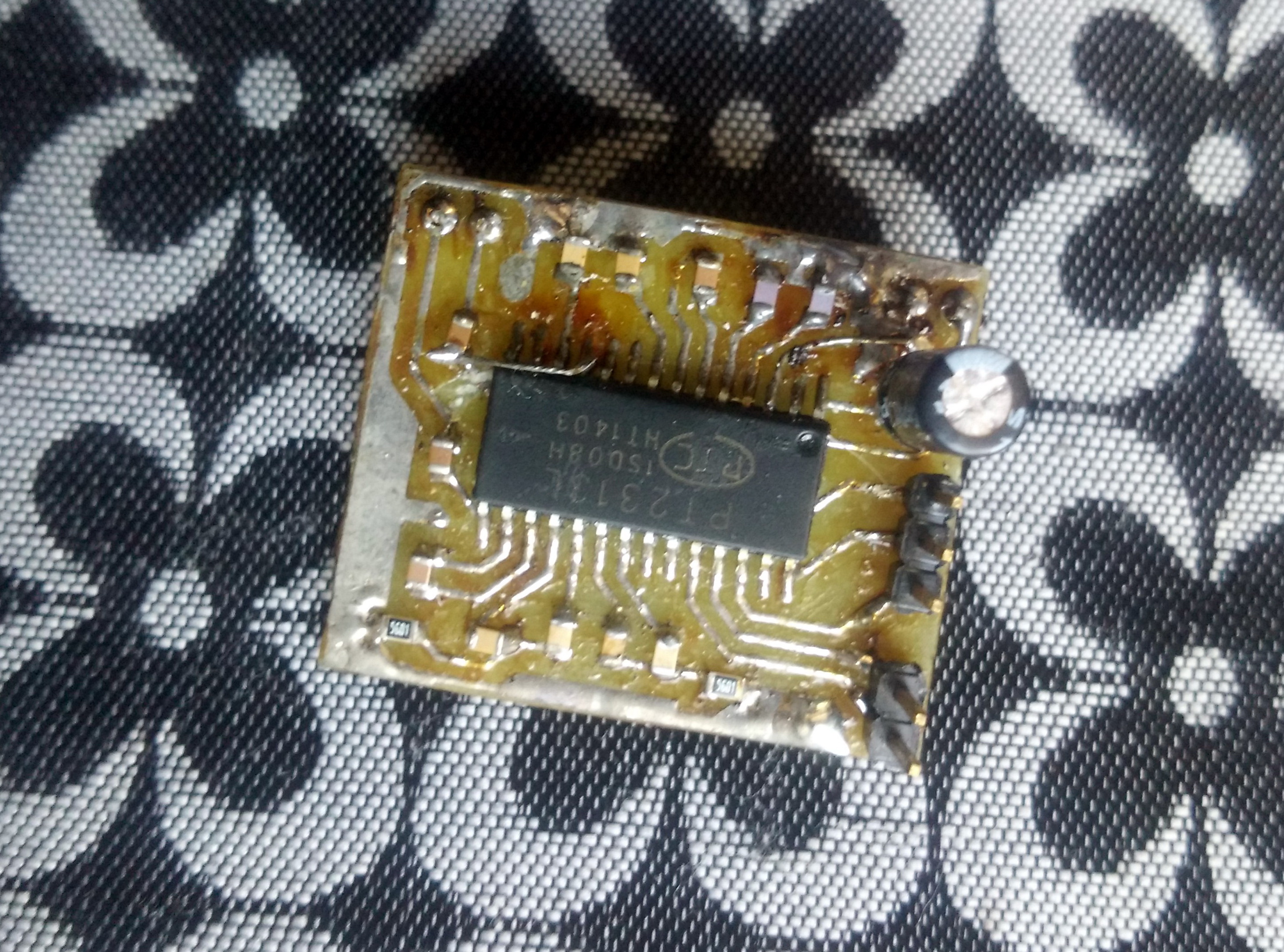
I had PT2313 chips (analog of TDA7313) so I used them as audio processor with i2c interface. This is an old prototype:
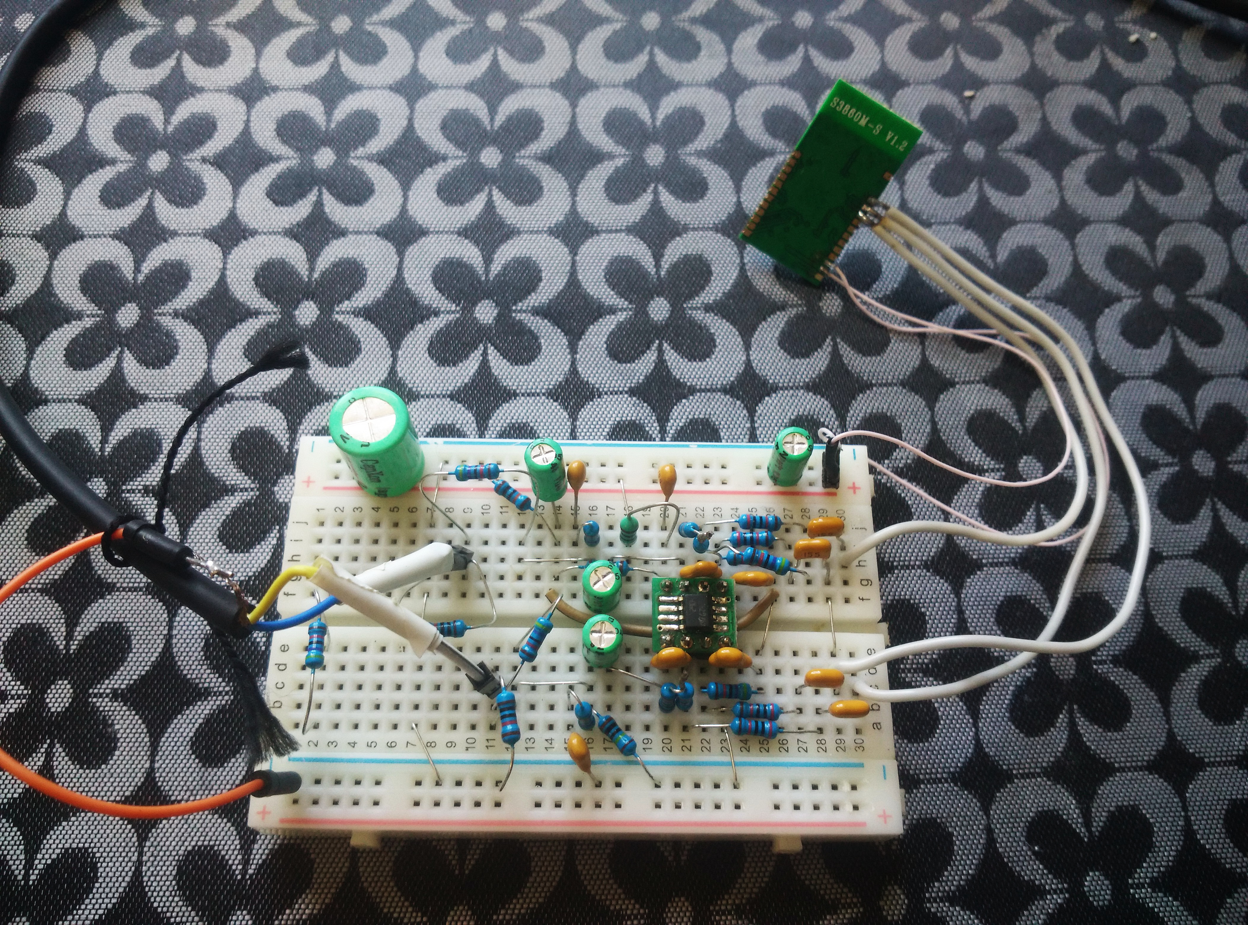
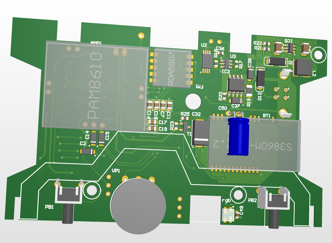
I had an S3860M-S bluetooth module so I used it. Though it has strange output which is not compliant so we must use opamp circuit. I tried to test it on the breadboard. Not HI-FI but not bad:
I've never used RDA5807M fm-radio module but I hope it works as declared.
I don't know how it's possible to tune radio without a screen and with one button so I decided to replace one button with an IR receiver. Hope it's a good decision.
I put an ordinary CH340G usb-uart chip but I really didn't know which socket to use. It would be excellent to use a micro-usb socket like in all mobile phones but even if I try to mount vertical micro usb it will be only 5-6mm height instead of 16mm old socket height. Moreover vertical micro-usb doesn't look very reliable. But the following day I found an easy and reliable solution. It is a vertical USB B socket! It is 16mm height and has nearly the same dimensions. So we can use any USB-B -> USB A cable to connect the device with standard power supply or to program a microcontroller!
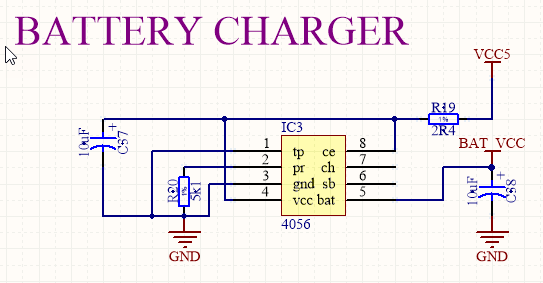
I do not know which battery I will use (we have enough space and I am sure I will find a suitable Li-Ion cell) but I know a tested controller solution. DW01 + FS8205A as a discharge controller and TP4056 as a charge controller. It is not perfect but cheap and easy.

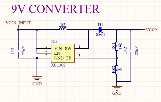
I had some PAM8610 amplifier boards so I decided to use them. It requires 9V power supply (PT2313 requires too) so we need a step-up. No problem, sx1308 is a reliable and cheap solution with high operated frequency so we do not need a very large inductor (not suitable for hi-fi, but it is not hi-fi :) ).
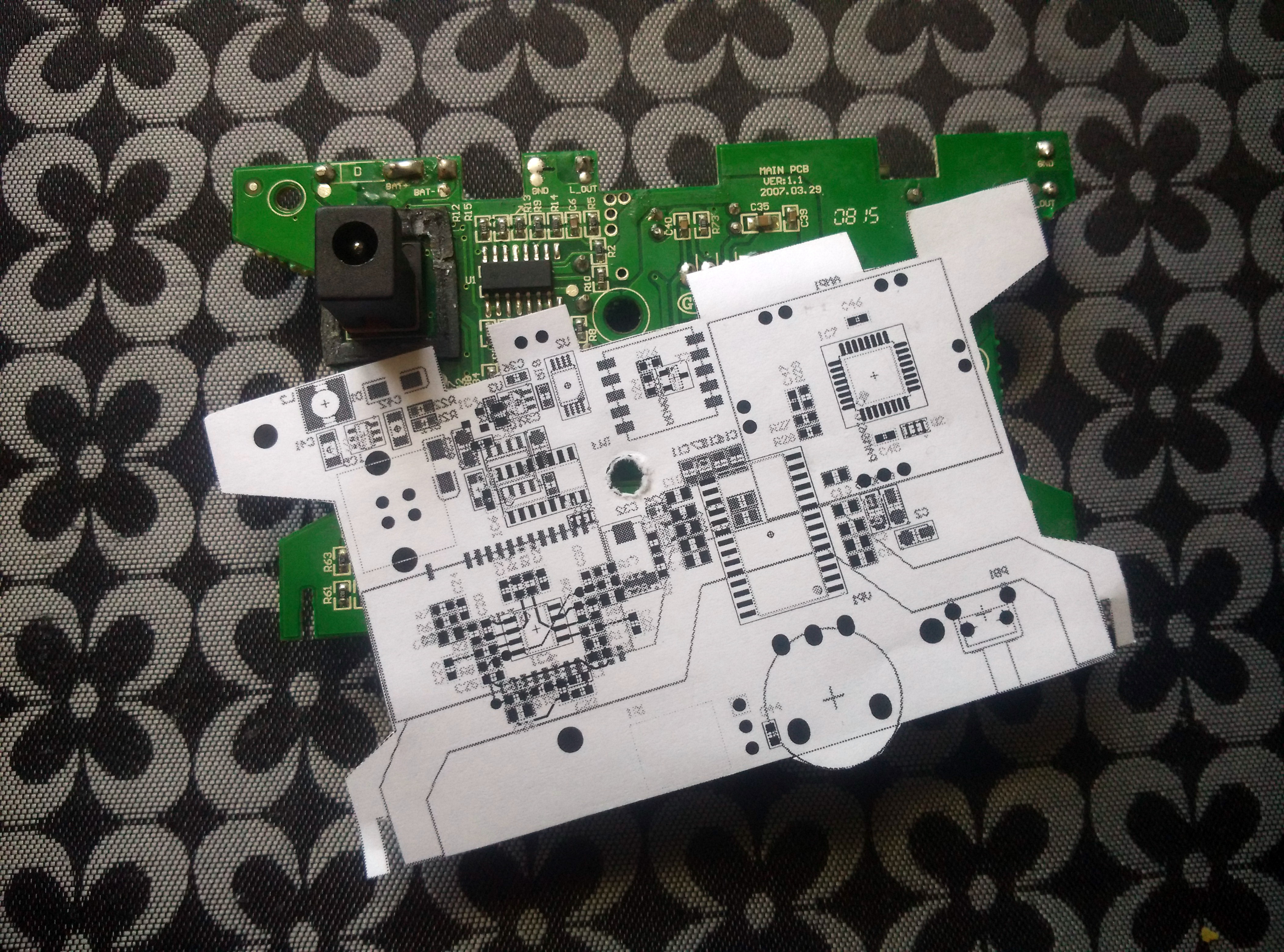
Buttons, wheel, board shape and so on... very difficult for any device. But this device has absolutely non standard controls and shape. Hope I found all what I need but will check twice before ordering the board.
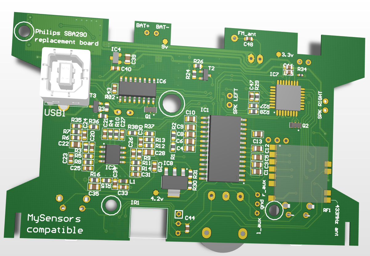
After I tried to route the project I found some things. At first I found a logic error. S3860M-S works under 3.6V in a very unstable way. It's very strange because the chip requires only 1.8v... may be it's eprom or other surprises on the module board :( So it is nececcary to use 4-4.2V power supply. Not a very trivial task because battery level is lower, main power supply level is higher. Moreover I didn't have enough space to correctly layout one more switching converter. So I just put LDO, it's not effective but it's not a crime (~26ma). Second... I routed the board carefully so I have enough space near atmega for RFM69. HELLO MySensors network! I am not sure which tasks I plan to solve using mysensors environment but I fitted RFM radio onboard and changed the remaining non controled power lines to be able to down the device to sleep mode with relatively low power consumption ;)
Now I need to check the board, adapt it a little for debugging and tuning and order it (unfortunately I have no time and conditions to create pcb at home from scratch). If it works (at least the majority of functions), I will move forward with software! :)
LIST OF REFERENCE
- PT2313 brief http://pdf.datasheetcatalog.com/datasheet/PrincetonTechnologyCorporation/mXrwsxv.pdf
- TDA733 datasheet http://www.promelec.ru/pdf/tda7313.pdf
- CH340G datasheet https://www.insidegadgets.com/wp-content/uploads/2016/12/ch340g-datasheet.pdf
- DW01 datasheet and appnote https://cdn.sparkfun.com/assets/learn_tutorials/2/5/1/DW01-P_DataSheet_V10.pdf
- TO4056 datasheet https://dlnmh9ip6v2uc.cloudfront.net/datasheets/Prototyping/TP4056.pdf
- SX1308 datasheet https://abc-rc.pl/templates/images/files/995/1470745126-1014430-164206430.pdf
- PAM6810 datasheet https://www.diodes.com/assets/Datasheets/PAM8610.pdf
- RDA5807 breaf https://www.futurashop.it/Allegato_PDF_ENG/2846-RDA5807M.pdf
- S3860M-S datasheet and appnote http://forum.amperka.ru/attachments/bt-pdf.2958/
- SK6812 mini datasheet https://cdn-shop.adafruit.com/product-files/2686/SK6812MINI_REV.01-1-2.pdf


