@EdCali sorry I don’t understand. I don’t know how this device is designed.
A very low current (double) stand alone uA meter to tune MySensors battery nodes..
Originaly intended to be a MySensors remote measurement node I de'MySensor'ized this project because it is more usefull on the workbench. It is disigned for measuring the very low currents of MySensors battery nodes. I own several Ampere meters including the famous µCurrent. Many of these are not accurate enough or need a lot of wiring and additional equipment (µCurrent). I just wanted something simple and stand alone.
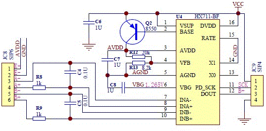
The main component is the low cost HX711 weight scale 24 bit AD converter. This ADC is purposed to translate the small changes in resistive weight sensors. There are many publications to be found on the weight scale application. In essence it is a 2 channel differential ADC with a few extra like 50/6 Hz noise canceling and internal voltage reference. That is how it is used in this sub 10€ double µA meter purposed for MySensors battery powered node tuning.
Some characteristics:
- range channel A: ± 20mA 5½-6½ digit µA
- range channel B: ±40mA 5½-6½ digit µA
- burden voltage 1µV/1µA (internal resistance 1Ω)
- 'patch panel' on the connectors.
- easy calibration.
- ~100ms update rate to be able to 'see' power fluctuations (like radio communication)
- moving average reading (16 samples) and error indication.
- can be morphed to other functions like mV meter/ mOhm meter in different ranges by adding changing a few components.
A few remarks and warnings
- There is no protection on the input. In normal use this won't be a problem. The 1 ohm shunt will protect against high voltages on the input.
- The circuit has to be "floating". Do not share the ground or Vcc with the device under test (DUT) You need to connect it to an other power supply than the measured circuit. (I use a USB power bank)
- Alhough the HX711 is a 24 bit converter with amplification of 32/64/128 times this is not the resolution you get. The circuit is sensitive to noise and temperature. In the configuration used with 1 ohm shunt you can can expect a sensitivity of around 100nA. If you want more sensitivity you can change the shunt to 10 /100 /1000 ohms. (I can't think of any purpose though)
- Because the HX711 (and the resistors) are sensitive to temperature you can expect some drift. To have best results you give it a few minutes of warming up time and then reset the offset (press and release the button).
Operation (assuming you did the calibration)
- power the meter via USB and use a separate power supply (floating, like a standard multimeter)
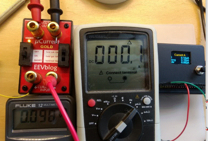
- let it stabilize for a few minutes and press/ release the button (= calibrate offset)
- Connect the device under test. I used a shared positive (hot) for both channels to be able to have a common ground in the circuit.
- Changing the channels can be done with a long press. (A -> B -> A+B -> etc.)
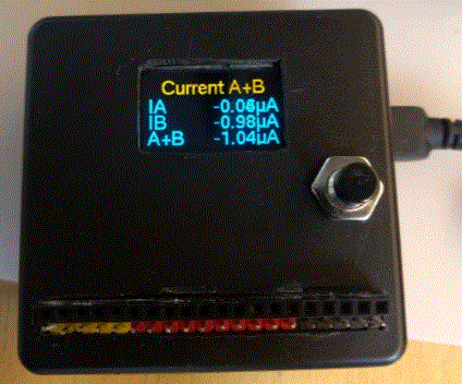
- The display shows the current current ;-), the average current in 16 readings and ann error indication. in A+B mode only the current and the A en B currents added.
Calibration (before first use)
- Set the sketch calibration values to 1.0f
- Power to node; let it stabilize for a few minutes and reset the offset (press/ release button)
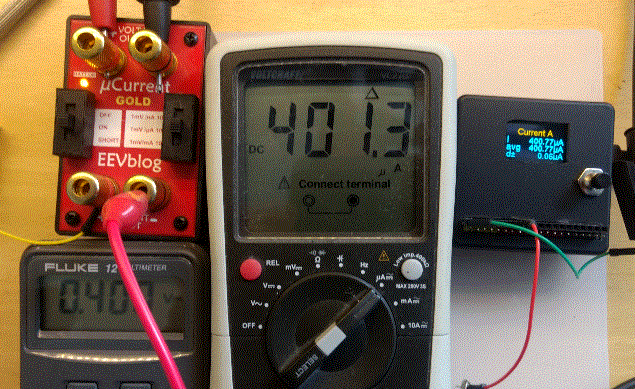
- For channel A: apply a current of around 100uA to 1mA in series with a ampere meter (multi meter).
- Note the measured multimeter value and the (avg) value in the display (just round to an average stable reading)
- Repeat 3 and 4 for channel B.
- divide the display 'currents' by the multimeter currents and change the corresponding values in the sketch.
- Upload the sketch and Done!
A little theory
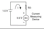
For a current meter the internal resistance causes a "burden voltage" expressed in V/A (mV/mA.) which influences the measurement.
For the famous "ucurrent" meter this value is 10ohm or 10mV/mA (in the uA range). A typical MySensors (nrf24) 'send' current of ~16mA will cause a voltage drop of 160mV. A typical multimeter in the uA range has a burden voltage of > 100mv/mA (100ohm) and will likely cause a MySensors battery node to malfunction when sending (1.6V drop in supply voltage).
This uA meter has a burden voltage of 1mV/mA (1 ohm) only! This results in ~16mV drop for a typical send and can safely be ignored.
Stability in the sub uA (nA) range is an issue because of temperature drift and all kinds of galvanic potentials.
Building
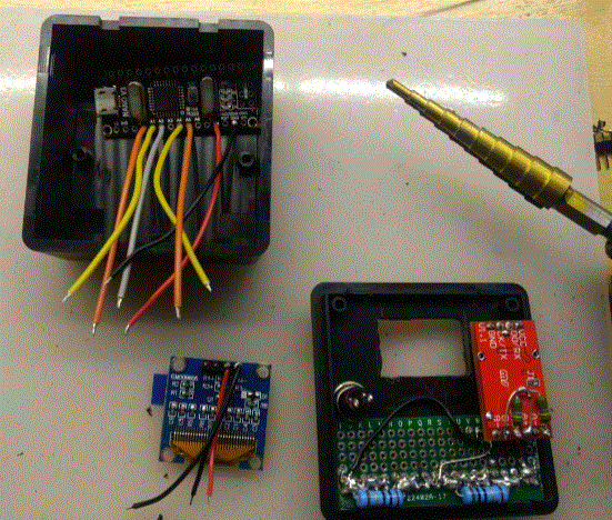
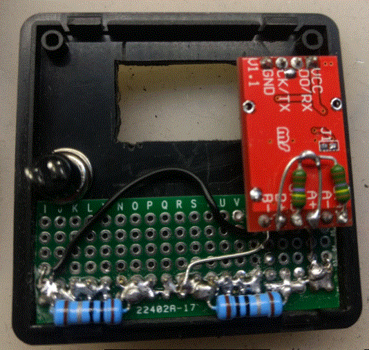
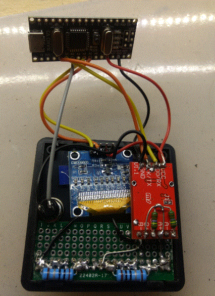
The circuit is simple so I just "spider wired" it together. The pictures will give you an idea on how I did it. Just be creative in how to fix it in the enclosure (I use strong double sided 3m thick tape mostly)
- Solder the pin headers male/female on a piece of breadboard. You can just use the bare minimum or (like I did) create some 'patch panel' area. I used colored pin headers to mark the differences (Channel A (-)/ Channel B (-)/ ChannelAB (+, common)
- Solder the shunt resistors (1 ohm) between the groups of pins A(-) to AB(+) and B(-) to AB(+) and connect all the pins you want connected.
- Solder the voltage divider resistors to the HX711 board Out(adc ref) to A+/B+ to Gnd. This voltage divider fixes one side the differential input to half the ADC reference voltage. 4 Solder the HX711 to Vcc(5v)/ Gnd/ A0/ A1 of the nano
- Solder the Button to A2 and Gnd of the nano
- Solder the I2C display to Vcc/ Gnd/ A4/ A5 (standard I2C)
- Upload the sketch and test the whole thing
- Glue it all together ; calibrate and have fun
The sketch (24 april 2017)
// uA meter with HX711
/*
 PROJECT: MySensors - uA meter with HX711
 PROGRAMMER: AWI
 DATE: 20170414/ last update:
 FILE: AWI_uA_meter.ino
 LICENSE: Public domain

Hardware: tbd Nano ATmega328p board w/ NRF24l01

Special:
    program with Arduino Nano

SUMMARY:
    Measures mV accross a shunt resistor ~ uA - channel A
    Measures mV on channel B
    Modes:
        - default: measure uV in full resolution (Stable reading only for 0.1uV)
        - other:
            A: channel A: default, amplification 128 - div 500: 0.1uV stable,  range +/- 20mV, (1ohm +/- 20mA, res 100 nA)
            B: channel B: amplification 32 - div 125: 100nA stable, range +/- 80mV,  (10 ohm +/- 8 mA, res 10 nA)
            AB: both channels:
        - uA - calibration: depending on the actual shunt:
            0.47 ohm -> 1 uV ~ 2uA, range -40 mA - 40 mA
            1 ohm -> 1 uV = 1uA, range -20 mA - 20 mA
            10 ohm -> 1 uv = 0.1uA
        - mV - calibration, depend on amplification
    Button switch:
        - Short press, reset current channel to offset 0 (keep terminals shorted, no need with uA ;-)
        - Long press, change channel A (uA) / B(uA)/ A & B (uA)

    Hx711 24bit weight scale sensor
        - Noise and temperature sensitive (x bit effective)
    OLED 128x64 display

Remarks:
    Size is large as result of font library for display
update:

*/

#include <U8g2lib.h>                                    // U8glib for OLED display
#include <Wire.h>                                         // I2C
#include <Button.h>                                        // https://github.com/JChristensen/Button
#include "HX711.h"                                        // local ADC lib https://github.com/bogde/HX711

const double calibrationFactorA = 488.5f ;                // calibration for channel A: set to 1.0 for known current and divide
const double calibrationFactorB = 122.5f ;                // calibration for channel B: set to 1.0 for known current and divide
long offsetChannelA = 0 ;                                // channel offsets for A and B (drifts) are calibrated at startup and on command.
long offsetChannelB = 0 ;

const uint8_t HX711_dout = A1 ;                            // HX711 data out pin
const uint8_t HX711_sck = A0 ;                            // HX711 serial clock
const uint8_t buttonPin = A2 ;                            // connects the button to select function and reset offset
const unsigned long longPress = 3000UL ;                //    - long press set reference temperature - in ms                                                //     - when alarm, short press resets alarm
Button myBtn(buttonPin, true,  true, 40);                // Declare the button( pin, pullup, invert, debounce ms)

enum convertMode_t {channelA, channelB, channelAB} ;    // measurement modes, 32 port B / 128 port A / A & B

HX711 scale;                                            // instantiate ADC

// U8G instantiate, Change this constructor to match the display!!!
U8G2_SSD1306_128X64_NONAME_1_HW_I2C u8g(U8G2_R0, /* reset=*/ U8X8_PIN_NONE);   // All Boards without Reset of the Display

const int nettReadingsSize = 16 ;                         // the number of readings to determine the average and calculate variance/ accuracy
double lastReading, lastReadingB ;
double nettReadings[nettReadingsSize] ;                 // store the rolling average of readings
int nettReadingPointer = 0 ;

convertMode_t convertMode = channelA ;                    // default channelA

void setup() {
    Serial.begin(115200);

    // u8g setup
    u8g.begin() ;
    u8g.setFont(u8g2_font_helvR14_tf);                    // 'r' = reduced (or 'n' = numeric) font only for size
    //u8g.setFont(u8g2_font_profont15_tf);                    // 'r' = reduced (or 'n' = numeric) font only for size

    Serial.println("AWI uA meter");

    // HX711.DOUT    - pin #A1
    // HX711.PD_SCK    - pin #A0
    // if parameter "gain" is ommited; the default value 128 is used by the library
    //   64 & 128 is port A ; 32 is port B
    scale.begin(HX711_dout, HX711_sck, 128);             // set port based on state of selection

    LCD_banner("Initializing") ;
    Serial.print("read average: \t\t");
    Serial.println(scale.read_average(20));              // print the average of 20 raw readings from the ADC

    getOffset();                                        // get the offsets (drift values)
    scale.set_offset(offsetChannelA) ;                    // set it for measured channel
    scale.set_scale(calibrationFactorA);                // this value is obtained by calibrating with known value; see the README for details

    Serial.print("read: \t\t");
    Serial.println(scale.read());                        // print a raw reading from the ADC
    Serial.print("read average: \t\t");
    Serial.println(scale.read_average(10));                // print the average of 20 readings from the ADC
    Serial.print("get value: \t\t");
    Serial.println(scale.get_value(5));                    // print the average of 5 readings from the ADC minus the tare weight, set with tare()
    Serial.print("get units: \t\t");
    Serial.println(scale.get_units(5), 3);                // print the average of 5 readings from the ADC minus tare weight, divided by scale
    Serial.println("Readings:");
}

void loop() {
    enum state_t {idleState, waitForRelease} ;            // define possible states
    static state_t state = idleState ;
    //Serial.print("one reading:\t");
    //Serial.print(scale.get_units(), 1);
    //Serial.print("\t| average:\t");
    //Serial.println(scale.get_units(30), 3);
    myBtn.read();                                        // read button state
    switch (state){
        case idleState:                                    // nothing
            if (myBtn.wasReleased()){                    // button released = silencePeriod
                state = idleState;                        // set silence period
                LCD_banner("Offset");
                getOffset();                            // get the offsets
            }
            if (myBtn.pressedFor(1000)){                // long press changes channel, need to wait for release
                // change channel and wait release
                switchMode() ;
                state = waitForRelease ;
            }
            break ;
        case waitForRelease:
            if (myBtn.wasReleased()){                    // button released return to idle
                state = idleState;
            break ;
        }
    }
    // get ADC readings dependent on setting: read A, B or A & B
    // only A reads has average buffer when A&B mode is selected
    if (convertMode == channelA){
        scale.set_gain(128) ;
        scale.set_offset(offsetChannelA) ;
        scale.set_scale(calibrationFactorA );            // set division to A value and set mode to A
        lastReading = scale.get_units(32) ;             // get value (average 32 readings)corrected with scaling
        nettReadings[nettReadingPointer] = lastReading ;    // store readings in averagebuffer
        nettReadingPointer = (++nettReadingPointer) % nettReadingsSize ; // increment and wrap
        LCD_local_display();
    } else if (convertMode == channelB){
        scale.set_gain(32) ;
        scale.set_offset(offsetChannelB) ;
        scale.set_scale(calibrationFactorB);            // set division to B value and set mode to B
        lastReading = scale.get_units(32) ;             // get value (average 32 readings)corrected with scaling
        nettReadings[nettReadingPointer] = lastReading ;    // store readings in averagebuffer
        nettReadingPointer = (++nettReadingPointer) % nettReadingsSize ; // increment and wrap
        LCD_local_display();
    } else if (convertMode == channelAB){                // if both channels average 128 readings iso 32 (no buffer)
        scale.set_gain(128) ;
        scale.set_offset(offsetChannelA) ;
        scale.set_scale(calibrationFactorA);            // set division to A value and set mode to A
        lastReading = scale.get_units(32) ;             // get value (average 128readings)corrected with scaling
        scale.set_gain(32) ;
        scale.set_offset(offsetChannelB) ;
        scale.set_scale(calibrationFactorB);            // set division to A value and set mode to A
        lastReadingB = scale.get_units(32) ;             // get value (average 128readings)corrected with scaling
        LCD_local_displayAB();
    }
    //scale.power_down();                                   // put the ADC in sleep mode
    //delay(500);
    //scale.power_up();
    //delay(100);
}


void LCD_banner(const char *s){
/* prints all avaiable variables on LCD display with units
    input: all "last" variables
*/
    u8g.firstPage();
    do {
        int strWidth = u8g.getStrWidth(s) ;                // get the length of the string to determine print position
        u8g.drawStr((128- strWidth)/2, 40, s ) ;            // print right aligned
    } while (u8g.nextPage()) ;
}


void LCD_local_display(void){
/* prints all avaiable variables on LCD display with units
    input: all "last" variables
*/
    char buf[21];                                          // buffer for max 20 char display
    char lastNettBuf[14];
    dtostrf(lastReading, 10, 2, lastNettBuf);            // Convert real to char
    char averageNettBuf[14];
    dtostrf(nettReadingsAverage(), 10, 2, averageNettBuf);    // Convert real to char
    char spreadNettBuf[14];
    dtostrf(nettReadingsSpread(), 10, 2, spreadNettBuf);    // Convert real to char
    Serial.print("Average: \t") ; Serial.print(nettReadingsAverage());
    Serial.print("\tSpread: \t") ; Serial.println(nettReadingsSpread());

    u8g.firstPage();
    do {
        snprintf(buf, sizeof buf, "Current %s", (convertMode==channelB)?"B":"A"); // Header
        int strWidth = u8g.getStrWidth(buf) ;            //   length of the string to determine print position
        u8g.drawStr((128- strWidth)/2, 14, buf ) ;        //   print middle aligned
        u8g.drawStr(0,31,"I") ;                            // Current
        snprintf(buf, sizeof buf, "%10s\xB5\A", lastNettBuf);
        strWidth = u8g.getStrWidth(buf) ;                //   length of the string to determine print position
        u8g.drawStr((128- strWidth), 31, buf ) ;        //   print right aligned
        u8g.drawStr(0,47,"avg") ;                        // Average current
        snprintf(buf, sizeof buf, "%10s\xB5\A", averageNettBuf);
        strWidth = u8g.getStrWidth(buf) ;                // get the length of the string to determine print position
        u8g.drawStr((128- strWidth), 47, buf ) ;        // print right aligned
        u8g.drawStr(0,63,"d\xB1") ;                        // delta +/-
        snprintf(buf, sizeof buf, "%10s\xB5\A", spreadNettBuf);
        strWidth = u8g.getStrWidth(buf) ;                // get the length of the string to determine print position
        u8g.drawStr((128- strWidth), 63, buf ) ;        // print right aligned
    } while (u8g.nextPage()) ;
}
void LCD_local_displayAB(void){
/* prints A & B channel on LCD display with units
    input: all "last" variables
*/
    char buf[21];                                          // buffer for max 20 char display
    char lastNettBuf[14];
    dtostrf(lastReading, 10, 2, lastNettBuf);            // Convert real to char
    char lastNettBufB[14];
    dtostrf(lastReadingB, 10, 2, lastNettBufB);            // Convert real to char
    char lastNettBufAB[14];
    dtostrf(lastReading +lastReadingB, 10, 2, lastNettBufAB);    // Convert real to char for added values
    u8g.firstPage();
    do {
        snprintf(buf, sizeof buf, "Current A+B");         // Header
        int strWidth = u8g.getStrWidth(buf) ;            //   length of the string to determine print position
        u8g.drawStr((128- strWidth)/2, 14, buf ) ;        //   print middle aligned
        u8g.drawStr(0,31,"IA");                            // Current A
        snprintf(buf, sizeof buf, "%10s\xB5\A", lastNettBuf);
        strWidth = u8g.getStrWidth(buf) ;                //   length of the string to determine print position
        u8g.drawStr((128- strWidth), 31, buf ) ;        //   print right aligned
        u8g.drawStr(0,47,"IB");                            // Current B
        snprintf(buf, sizeof buf, "%10s\xB5\A", lastNettBufB);
        strWidth = u8g.getStrWidth(buf) ;                //   length of the string to determine print position
        u8g.drawStr((128- strWidth), 47, buf ) ;        //   print right aligned
        u8g.drawStr(0,63,"A+B");                        // Current A + B
        snprintf(buf, sizeof buf, "%10s\xB5\A", lastNettBufAB);
        strWidth = u8g.getStrWidth(buf) ;                //   length of the string to determine print position
        u8g.drawStr((128- strWidth), 63, buf ) ;        //   print right aligned
    } while (u8g.nextPage()) ;
}

// calculate average of nett readings
double nettReadingsAverage() {
    double sum = 0;
    for (byte i = 0; i < nettReadingsSize; i++) {
        sum += nettReadings[ i ];
    }
    return sum / nettReadingsSize;
}

// calculate spread of nett readings (+/-)
double nettReadingsSpread() {
    double minReading = nettReadings[0];
    double maxReading = minReading ;
    for (byte i = 1; i < nettReadingsSize; i++) {
        if (minReading > nettReadings[ i ]){
            minReading = nettReadings[i] ;
        }
        if (maxReading < nettReadings[ i ]){
            maxReading = nettReadings[i] ;
        }
    }
    return (maxReading - minReading)/2 ;
}

// switch the mode
void switchMode(){
    if (convertMode == channelA){
        convertMode = channelB ;
    } else if (convertMode == channelB){
        convertMode = channelAB ;
    } else {
        convertMode = channelA ;
    }
}

// assuming both channels are shorted, calculate the offset values for channel A and B
double getOffset(){
    scale.set_gain(128) ;                            // get channel A
    offsetChannelA = scale.read_average(32) ;        // average 512 readings for offset
    Serial.print("Offset A: \t") ;
    Serial.println(offsetChannelA);
    scale.set_gain(32) ;                            // get channel B
    offsetChannelB = scale.read_average(32) ;        // average 512 readings for offset
    Serial.print("Offset B: \t") ;
    Serial.println(offsetChannelB);
}
 Micro (nano) ampere meter (double)

