Hello all,
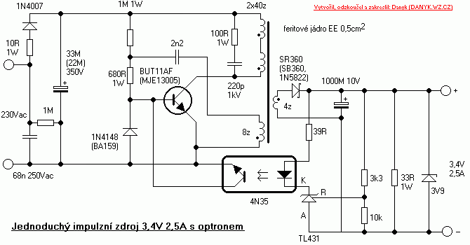
I studied a little bit more this part of the circuit and it's a standard self oscillating flyback converter or a ringing choke converter as others call it. Indeed it provides the most compact solution for space constrained designs. But all of this comes at a cost: it's difficult to obtain a stable circuit and it has to be tuned by trial and error - at least this is what the literature says.
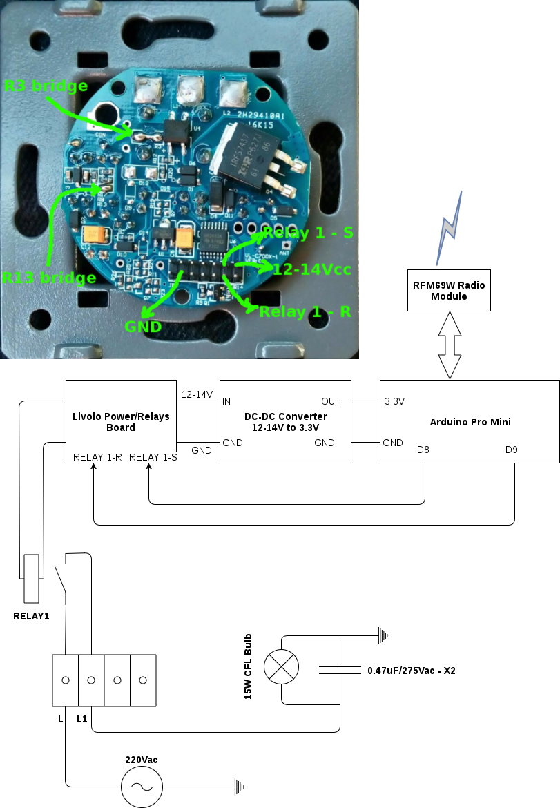
I'm not a switching power supplies expert here(even though I want to learn more about SMPS's in general but my time is limited for now) but I've come to a conclusion: it's difficult to tune this or to change the existing circuit to accommodate the mysensors circuits power requirements. I tried various combinations using sleep schemes and to change the flyback converter components as other mentioned in the mysensors forum and indeed I can power up my custom design that is presented in this thread BUT it's NOT STABLE. From time to time the switching transistor(mje13003) burns out and this is because I removed the resistor placed at the input of this power supply - near the bridge rectifier and replaced it with a wire(this is not the same resistor as @Lukaspp replaced from the base of the transistor which is the startup resistor for the flyback converter).
Now the only purpose that I imagine for this resistor is to suppress the transients - but it has a big value(100Kohm) which limits the current to a non-usable value for our purpose. I know that there are other solutions to overcome the transients but they are either bulky or too slow for this(correct me if I'm wrong here).
More than that let's not forget that we have 2 power supplies here and when the lights go on the first supply(flyback) input gets shorted by the relays contact(I have the relays variant btw not the one with triac) so I'm thinking that other transients appear here as the primary inductor doesn't like that as far as I know - so I assume the above mentioned resistor of 100Kohm comes into play here too. Another role for it would be to limit the inrush currents. I played with that value too but it needs to be very low to have something stable and I got a value around 200ohms but that doesn't help as it's too low and after some time the resistor burned up and saved my transistor :simple_smile: .
Now with all the tricks in the world and tuning the flyback converter to give more current this won't help as again let's not forget we have a SERIES circuit here so without external intervention we can't achieve that(only if we break somehow the laws of physics or maybe my thinking is limited :simple_smile: ). In this case the external capacitor placed across the light bulb comes into play to supply enough current to the standby circuit which is our flyback converter over here. I played with that one too and from 0,47uF I got to 4.7uF to have a decent result - but this one gets bulky and more expensive from obvious reasons. And let's not forget that the light bulb itself has some impact overall because this is the actual LOAD that we want to control and there are various light bulbs over there with various requirements. More than that they have their power supply embedded which in most of the cases is a(you guessed maybe): a self oscillating FLYBACK CONVERTER or similar. So this one too has inrush currents, transients which are sensed down the line to our dear Livolo switch and affects my custom board stability again :simple_smile: - isn't life beautiful? :simple_smile:
So far these are the results of my trials and none of them proved to be stable so I kinda gave up on this and will try to use a normal powering scheme somehow(as Sonoff switches with a battery powered touch switch on the wall). Not the best solution of all but this is what you get when the infrastructure wasn't thought for this scenarios from the beginning.
The Livolo guys thought of all of this I assume so that's why they stayed only with a simple circuit - a PIC mcu which maybe sleeps most of the time and a simple radio receiver which draws around 5mA or even less - so yeah that's why this works and it's stable in its original form.


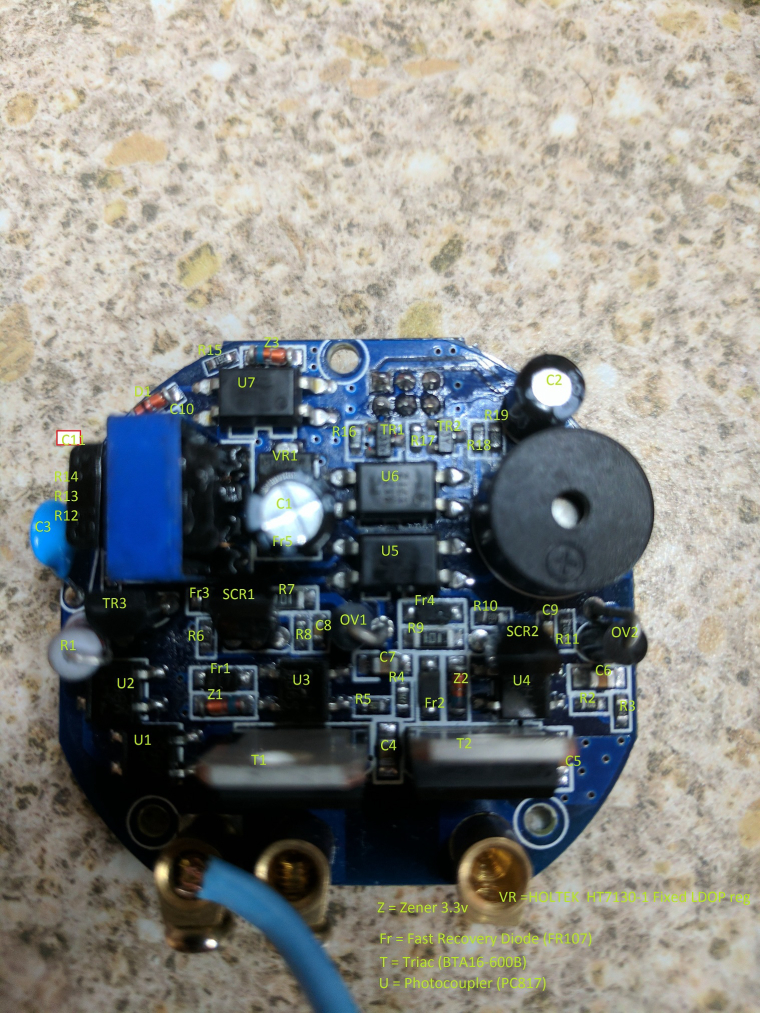
 Livolo 2 channels 1 way EU switch(VL-C700X-1_Ver_C2)


