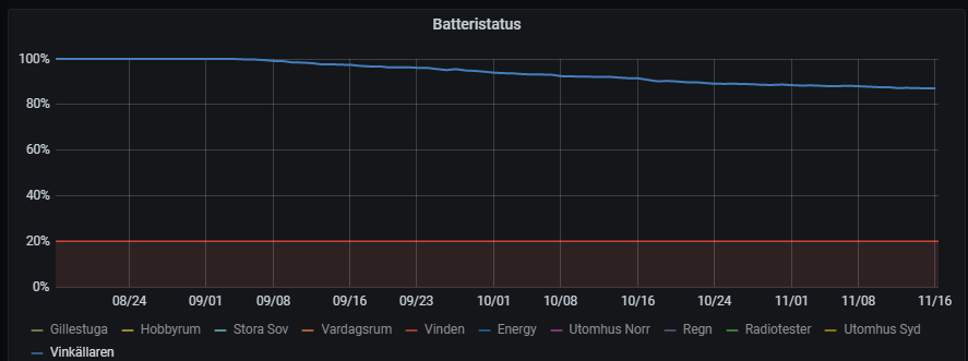
@hlehoux - nice once! Thanks for sharing!
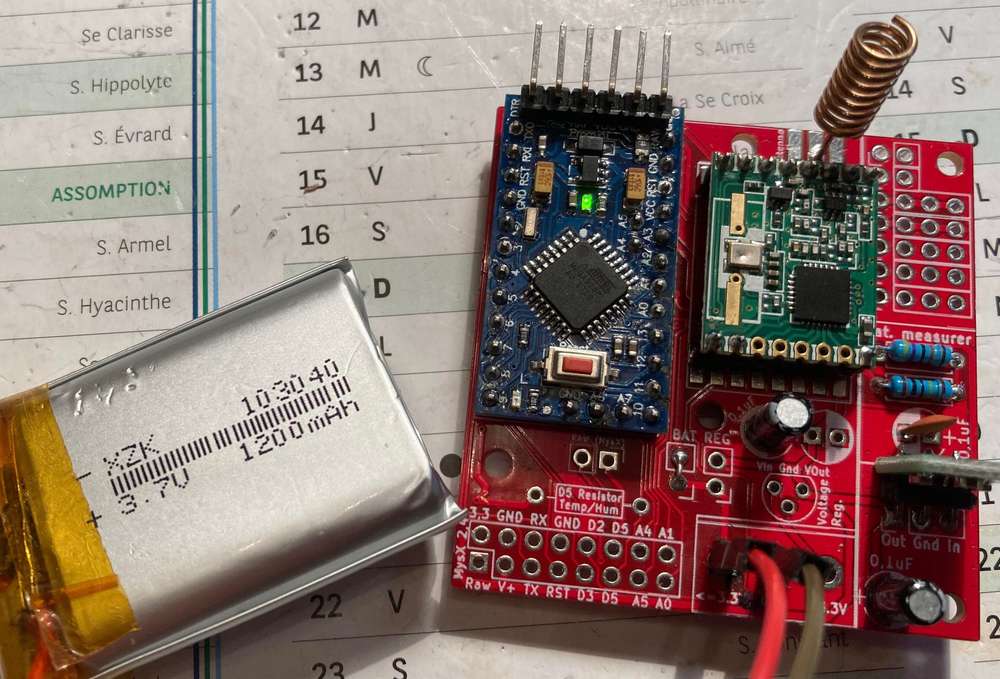
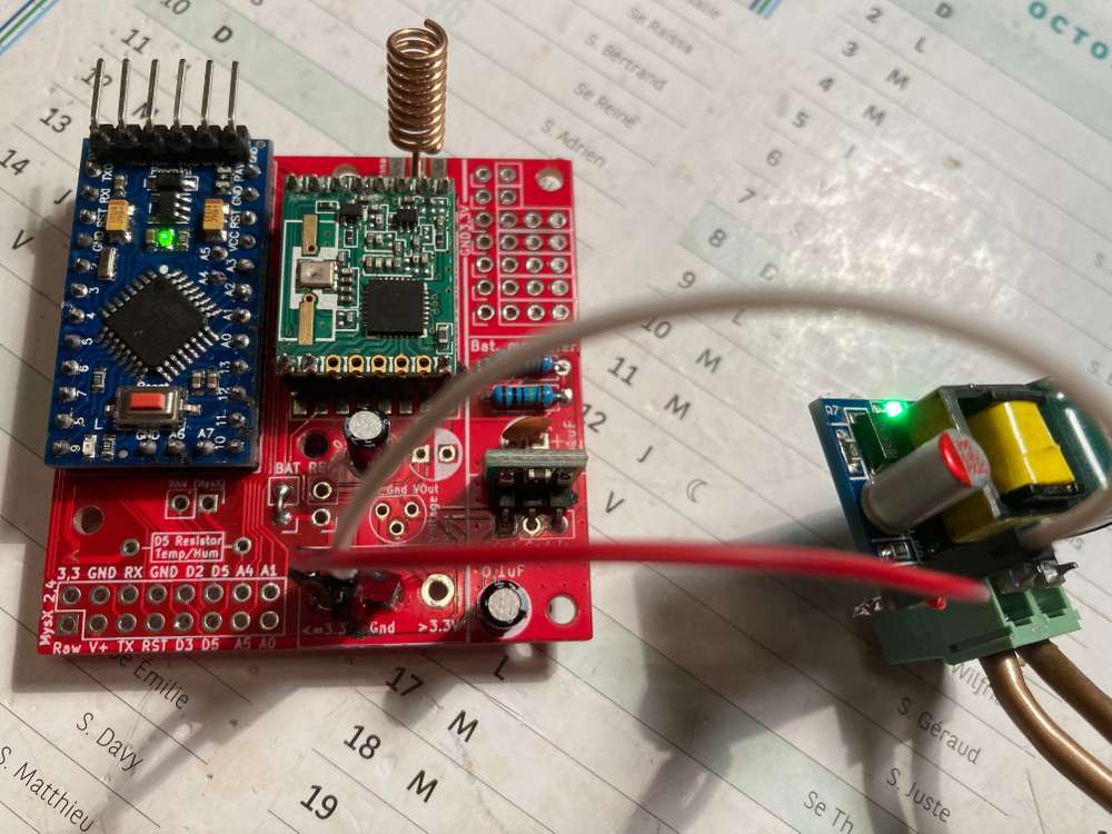
This is a PCB for all beginners who want to quickly build the nodes described in the MySensors website! It can be used with regulated power or batteries and only have basic components. Its a PCB for all newbies that want to do basic sensor/actuator nodes like myself out there...
This is the RFM69(HW/W) edition of EasyPCB! If you want the original EasyPCB with Nrf24l01+ transceiver - go here.

Why?
So pretty much this PCB covers all the basic stuff documented in the MySensors website! This cuts my work with one node from a couple of hours (soldering wires) to 20min.
What?
Only easy to solder components with good space in between. Only basic functions (Pro Mini 3,3v, Radio, Input for sensors and if battery powered booster and voltage divider) Some inputs for all the normal sensors used in the build section. 5x5 or 3x5 depending on function and dynamic in what power you use (Battery, 3.3v or >3.3v (requires voltage regulator). Note, this edition can only handle Pro Mini 3.3v and NOT 5v
How?
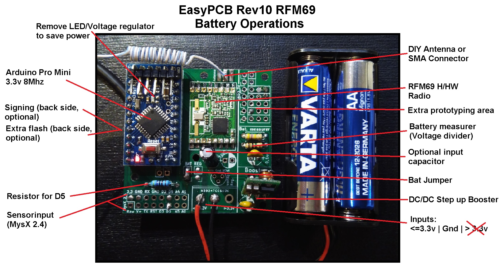
Battery (2xAA or similar)
5x5cm
- Arduino Pro Mini 3.3V
- Radio RFM69 H or HW
- Antenna
- Voltage divider - Measuring and Reporting Battery Level - (My code)
- Boost converter/step-up converter (0.9 - 3v > 3.3v) (Use a good quality booster! Cheap boosters create a lot of noise which can interfere with radio and other components. Alternative build without the booster and lower BOD)
- Caps/Resistors/Pinhead (jumper)/Screw terminal (optional)
- Sensors are possible to attach to the left (Gnd x 2, VCC, D3 (with or w.o resistor), D4, D5, A4, A5)
- Use BAT jumper and make sure you have a booster attached to close the circuit. Connect the batteries to right input marked "<= 3.3v"
Power consumption (without booster) in MySensors sleep() mode (Ver 2.2) was measured to 5,2uA which will last a node (depending on how often it transmits) a long time!
Regulated 3.3v
3x5cm (cut PCB)
- Pro Mini 3.3v
- Radio RFM69 H or HW
- Antenna
- Caps/Resistors/Pinhead (jumper)/Screw terminal (optional)
- Sensors are possible to attach to the left (Gnd x 2, VCC, D3 (with or w.o resistor), D4, D5, A4, A5)
- Use REG jumper and connect 3.3v to right input marked "<= 3.3v"
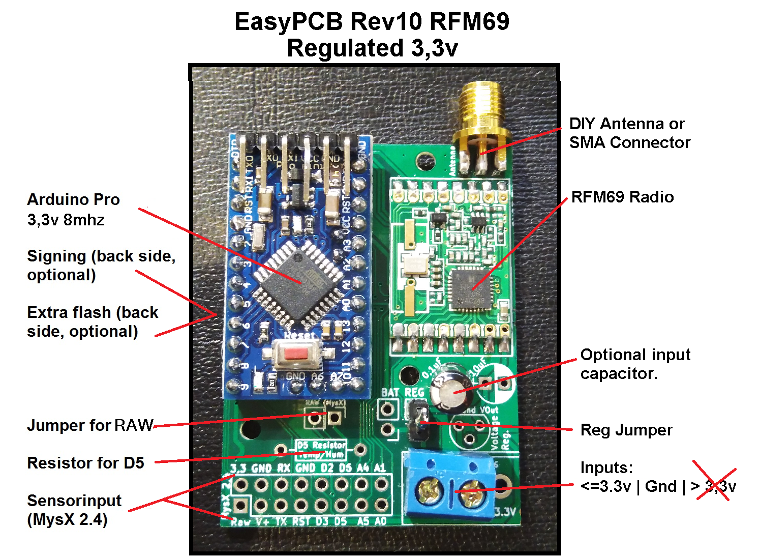
Only the lower capacitor marked 0.1uF affects the RFM69 module! The capacitor marked 10uF only affects the input of the voltage regulator.
Higher voltage than 3.3v
3x5cm (cut PCB)
- Pro Mini 3.3v
- Radio RFM69 H or HW
- Antenna
- Caps/Resistors/Pinhead (jumper)/Screw terminal (optional)
- Sensors are possible to attach to the left (Gnd x 2, VCC, D3 (with or w.o resistor), D4, D5, A4, A5)
- Voltage regulator to handle your input voltage and regulate it down to 3.3v
- Nu jumper should be connected and connect your power to left input marked "> 3.3v"

Battery without a step-up booster (advanced users)
3x5cm (cut PCB)
To be able to achieve this you need to reprogram the atmega bootloader/fuses and lower the BOD!
- Pro Mini 3.3v
- Radio RFM69 H or HW
- Antenna
- Caps/Resistors/Pinhead (jumper)/Screw terminal (optional)
- Sensors are possible to attach to the left (Gnd x 2, VCC, D3 (with or w.o resistor), D4, D5, A4, A5)
- Use REG jumper and connect 3.3v to right input marked "<= 3.3v"
With REG closed you will feed everything (Arduino, Radio and Sensors) with whatever voltage the battery holds. You can´t use any sensors which require higher voltage than the current battery status (without using a DC/DC Step up booster for the sensor). With this configuration, you can measure VCC supply level without external components [Library]. Lowest working voltage (depending on added sensors) will probably be the RFM69w module which can handle down to 1.8v. Do not use any DC/DC step-up booster or voltage regulator to feed the Arduino or radio!
To lower BOD you can use standard Pro Mini bootloader and change boards.txt to upload a new bootloader with lower BOD (Brown-out Detector - disables the chip at set voltage). See here for instructions.. This will give you some more battery (down to 2.2-2.4v?) but using the 8mhz external crystal will be out of specs below 2.4volt (Page 312 - Chapter 29.3). So it might be a good idea to run a bootloader @ 1mhz internal oscillator or 8mhz internal oscillator. Several users reports running the atmega chip below 2.4 volts @ 8mhz seems fine though and unless doing crazy stuff should not cause major issues. You need to try your application and evaluate as voltage drops. Personally I set my 0% battery calculation to 2.2v which works fine.
Build video
A great video by @wez on how to assemble the EasyPCB with Booster and Battery (timelapse). A good example on how to build modular which allows to remove or change hardware if something goes wrong/stops working or you just want to re-use the sensor in the future for something else.
A build video of a regulated 5v EasyPCB (nrf24l01+), including uploading a sketch for testing the radio and clearing the EEPROM.
More videos can be found looking at the Nrf24l01+ version. Its the same build except for another radio.
Antenna
You need to attach an antenna to the board. The antenna needs to be single core inside, not multi-wire like you can find in common dupont cable. Aside from not working without an antenna, transmitters can be damaged if they transmit without an antenna present. For this PCB you can either attach an SMA connector and buy an antenna with that connector or make do it yourself. There are a lot of tutorials out there, and for 433mhz I suggest this tutorial.
PCB Dimensions
5x3,5cm for cut PCB/regulated voltage and 5x5cm battery operations with extra prototyping space.
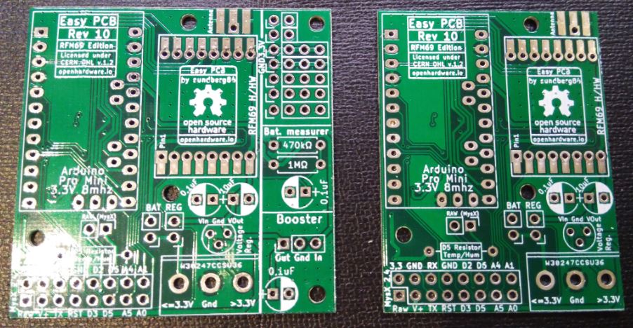
Jumpers
BAT: Short this if you are using batteries as power supply. It will activate booster circuit and power everything with a stable 3.3v. Make sure you have a corresponding DC/DC step-up booster to match your batteries to 3.3v
REG: Use this if you are using 3.3v regulated DC.
RAW: This is a MysX feauture. This cuts onboard Vraw source if daughterboard provides Vraw. This is only used when EasyPCB is connected to a daughterboard.
MysX 2.4
This is The MySensors expansion connector to which you can connect any daughterboard using this standard. This is also your main input/outputs for sensors and actuators so any wires can be connected accordingly. With this PCB as motherboard, you can use draughtboards if you need multiple copies and needs a quicker way to build - just like a shield on Arduino or Raspberry Pi.
If you want to create your own MysX daughterboard you can use this template (KiCad)
Example
Boxes / Enclosures
Here are images of a great box by @dbemowsk which fits EasyPCB + 2xAA and it can be found on thingiverse
Also a great box by barbuino here.
Case added in BOM (Stl file avalible) - with a internal part to fasten a 5x3 EasyPCB board with 2xAA holder on the back. Also a lid and a outer casing if needed.

Revision changes
2018-06-05 Rev 10 - RFM69 Edition
- MysX location changed to accept more MysX boards and align like Nrf24 version.
- Antenna location changed, radio rotated 180 degrees
- Optional signing chip added
- Optional SPI flash added.
- Extra pins aligned to 2.45 vertical & horizontal
- Relocated Extra + Bat Measurer some to allow more space to booster
- Pinholes added for RFM Radio
- Changed pull-up resistor from D3 to D5 to have one more pin for Interrupt
I want it!
Order 10pcs: Openhardware.io (Recommended!) and support me and MySensors! (It may say another rev. at the order page but this is not EasyPCB rev but the rev for the manufacturer. I always update the Gerber files for sale! Current = Rev 10)
Download from this page to get KiCad and Gerber files.
If you want a faster shipping time or fewer pieces you can order from me on Ebay.
Inspiration
https://1drv.ms/f/s!Ak7D1EWM7GXggvQ9mzJzWJSMir8sLA
(Note some photos are older revisions of the PCB)
** Projects **
- Serial Gateway
- Garden beer cooler
- Portable RFM69 Signal Scanner
- BME280 (i2c - Humidity/Pressure/temp) nodes
- Irrigation controller
- Finger print reader (battery)
- Bedside alarm clock
- Door + Flood sensor


