
FWIW, I used 1.55mm holes. There may be no perfect diameter since we don't even know for sure yet which lens will turn out best.
Yo! This project is still a Work In Progress. Instructions, board layouts and BOM might change!
This is a PIR sensor shield for NModule. It can use a simple AM/AS312 breakout board, or a standalone AM612 sensor to be able to set sensitivity and active/on duration. It also has a footprint for MAX44009 I2C light sensor.
Detailed instructions will be added after I receive the PCBs
| Name | Size | # Downloads |
|---|---|---|
| PRODUCT.txt | 110 B | 354 |
| LICENSE.pdf | 95.73 kB | 220 |
| NModule_PIR.GTO | 67.53 kB | 482 |
| NModule_PIR.GTL | 78.63 kB | 480 |
| NModule_PIR.GTP | 24.46 kB | 489 |
| NModule_PIR.GTS | 23.74 kB | 484 |
| NModule_PIR.TXT | 1016 B | 358 |
| NModule_PIR.brd | 51.41 kB | 562 |
| NModule_PIR.sch | 130.29 kB | 697 |
| NModule_PIR.GBO | 40.95 kB | 471 |
| NModule_PIR.GBL | 73.93 kB | 518 |
| NModule_PIR.GBP | 22.02 kB | 490 |
| NModule_PIR.GML | 22.02 kB | 470 |
| NModule_PIR.GBS | 23.42 kB | 526 |
| COPYRIGHT.txt | 428 B | 369 |
| License_howto.pdf | 55.06 kB | 216 |
-
 NeverDie commented 8 years ago
-
 Nca78 commented 8 years ago
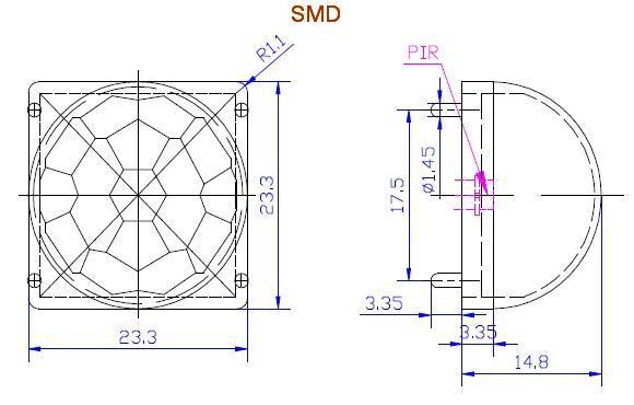
Regarding the holes it's strange because on my board I have the spacing a bit wrong but the holes are big enough. And I don't remember changing hole size when I fixed the spacing. I'll increase the size anyway as I see on the "datasheet" picture I posted in the other thread that the feet are supposed to be 1.45mm and my holes are only 1.2... Probably my lenses are not really matching the standard.
-
Nca78 commented 8 years ago
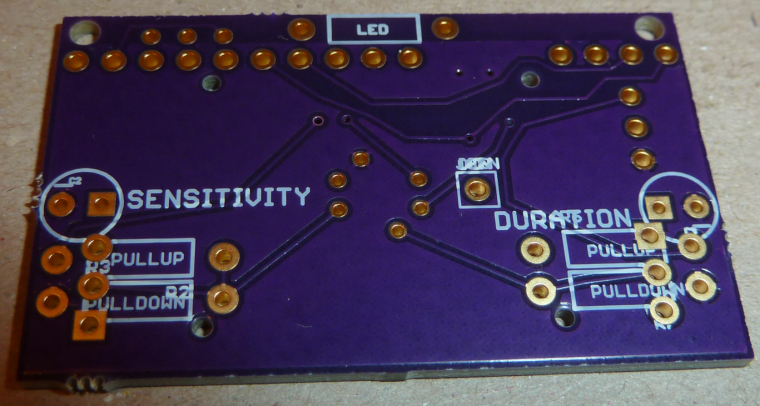
@NeverDie I think I know the reason for the silkscreen problem. When you upload please make a zip with all the gerber files but do not include the .brd file. I hide the "Name" layer when I export so I can place the component name where I want, with the size I want, or hide it to replace it with more interesting information. Still some details to fix in the silkscreen though...
When you upload the .brd file OSH park will take all layers in it and export them, including the name layer and it will mix up with the additional info I added. It's the same problem with the NModule board. -
NeverDie commented 8 years ago
@Nca78
I received the PCB today. Comments:-
At least for my lens, the holes are too narrow and I can't fit them in. I'll try boring bigger holes with a drill. If you want, I'll look up for you the hole diameter that I used on my primitive breakout board, because it fit just right (by pure luck I'm sure).
-
Lettering on the silkscreen appears to have some issues (see photo):
I'm still waiting to receive my AM612's, so nothing more I can really do right now.
-
-
Nca78 commented 8 years ago
@scalz said in
 NModule PIR sensor shield:
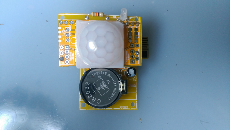
i wouldn't choose a CR2032 with a PIR (regarding lifetime...) but it looks nice

Just wanted to test it and this was the only NModule board that was completely soldered

It can use 2*AA or CR123 for PIR.And no, not looking so good I have butchered the boards when separating them from the panel

-
 scalz commented 8 years ago
i wouldn't choose a CR2032 with a PIR (regarding lifetime...) but it looks nice
too bad for the PIR sensor, not tried yet, i should receive some soon. not a problem on my side, i can use both analog & digital types on my board. Still curious to test those though -
Nca78 commented 8 years ago
So I made a test for the basic functionality of this shield (with 2s ontime and max sensitivity) and it works, but as I said in the other thread even with the SR501 lens it seems to have similar problem than the am312: some "blind" areas where it doesn't detect movement.
@NeverDie you will tell me when you receive the shield if the PIR fits better than on the PCB I made, as I fixed the footprint on the version that I uploaded on OpenHardware.io following discovery of PDF with exact measurements. It was a bit difficult to put in place on mine
")
-
NeverDie commented 8 years ago
Understood. In that case I'll make a barebones breakout board for the AM612 as a "Plan B". I figure the odds are good that at least one of our two boards should work!
-
Nca78 commented 8 years ago
@NeverDie said in
NModule PIR sensor shield:I don't mind sharing the risk. Did you run schematic verification on the PCB? In Diptrace, it's one of the simple tests that can be run to ensure that the PCB does correspond to the original schematic, and I presume Eagle has it as well. If ithe board passed that test, then I'm not overly worried.
I don't see the reason of such a test ? Schematic and board/pcb are linked in Eagle, everything I add in schematic is created on the board/pcb also. I just have to make sure all expected connections have a trace (no more "airwires") and make a design rules check to make sure I respect the rules set for PCB manufacturing.
So yes I did that but I could have made a mistake in the footprint or made a wrong connection on the schematic, some of the PCBs were finished late at night so there's a high probability to have a failure or two in the 8 shields.
-
NeverDie commented 8 years ago
I don't mind sharing the risk. Did you run schematic verification on the PCB? In Diptrace, it's one of the simple tests that can be run to ensure that the PCB does correspond to the original schematic, and I presume Eagle has it as well. If ithe board passed that test, then I'm not overly worried.