@LastSamurai Thanks, it looks great.
The MySensor homepage offers great resources on how to build your first very easy to use gateway (serial with an arduino nano/uno + some wires and an nrf) to get you going. Once you hit the point where your network has more than a hand full of nodes or you are planning to build a new network somewhere else you might want some more advanced gateways, like a wireless one or one with status leds and a stronger NRF24 for a better range.
This is the pcb I came up with to solve these "problems". An easy to use but still very powerful platform to build all kinds of gateways.
Features
This is what I designed this gateway pcb to do:
- it is still easy to solder (few components, most are modules like the arduino nano or the ESP8266)
- higher range: it supports a NRF2401+ PA LNA and has an oboard 3.3V converter to power it + some caps
- commonly used connectors: as a power input the board uses a micro usb breakout board, the arduino nano has a mini usb connection for data + power
- more feedback: it has 3 status leds, for reading/writing data and for errors
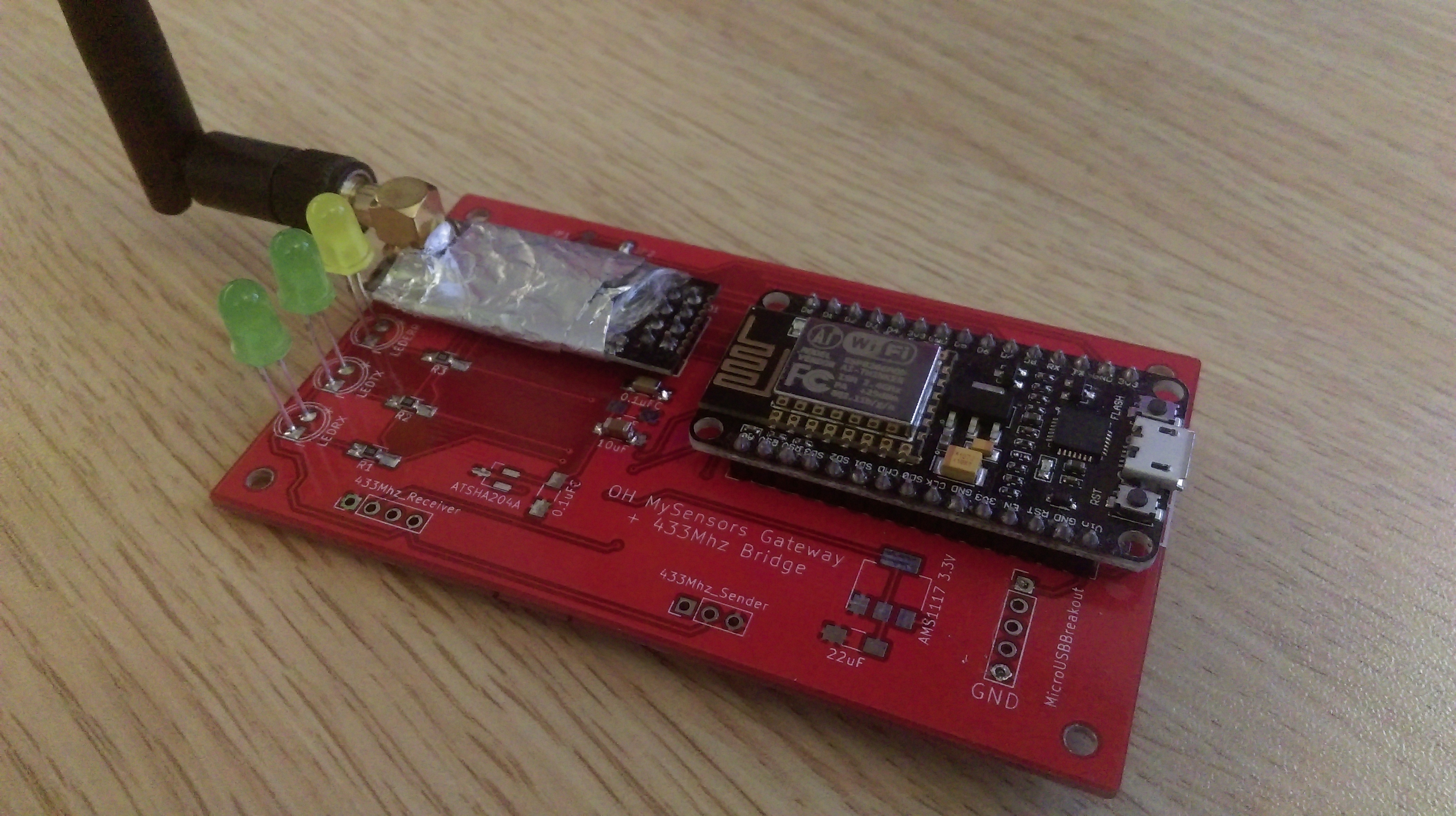
- wireless gateway: the pcb support either an arduino nano as a serial gateway or an NodeMCU (ESP8266 breakout board) as a wireless gateway!
- flexibility: for power you can either use a micro usb breakout board or solder directly to the board, you can also power the radio directly from the nano/ESP by closing jumpers. You can use a nano or a NodeMCU. You can use any 5mm status leds you want or none at all. You can use a normal NRF24L01 or the high power version... the choice is yours!
- 433Mhz support: as many cheap devices communicate via this frequency I also added slot for a receiver and a sender
- security: The pcb support software signing (well ... which one doesn't?) as well as hardware based signing via the ATSHA204a which can be placed on the board
Versions
Some possible version are:
Serial + 433Mhz
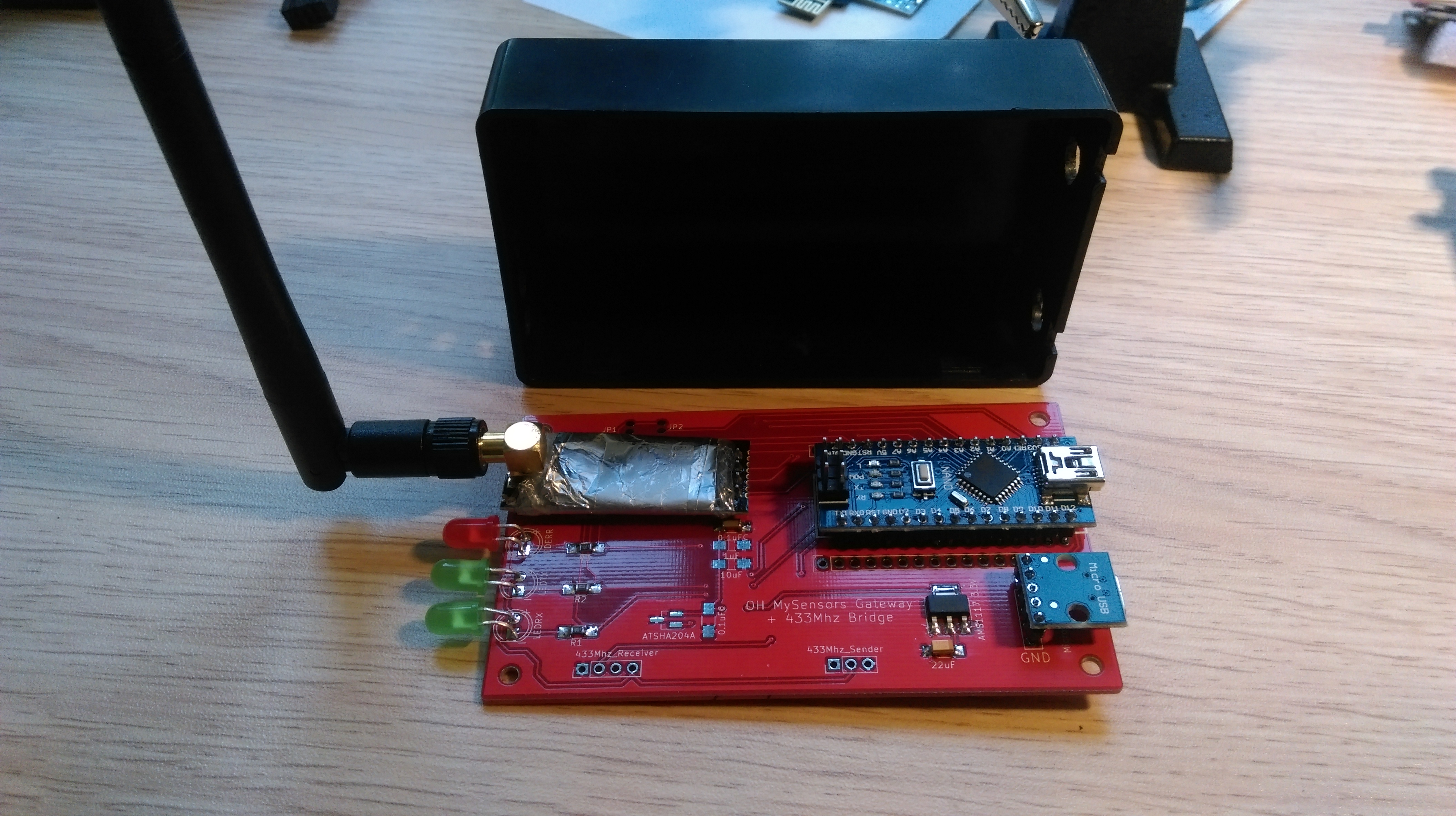
The main gateway of my current MySensors installation is using this board with an arduino nano, a NRF PA+LNA and a 433Mhz receiver. The code for this can be found in the code section. As a normal serial gateway the device is running great. Its even better than my old arduino uno based setup because of the high power NRF.
It also works as a 433Mhz gateway but I am having problems using both at the same time. If you can help here is the thread.
Wireless gateway
I am currently building another version for a new network that uses the NodeMCU and a high power NRF for a wireless gateway. You should be able to use the standard code for the wireless gateway. The leds are connected to: D0-Error, D1-RX, D3-TX.
Update: I have finally finisted my ESP8266 based build. This will be the gateway for a new MySensors network. This one is powered directly from the 3.3V converter of the ESP, no separate converter this time.

433Mhz to Mysensors gateway
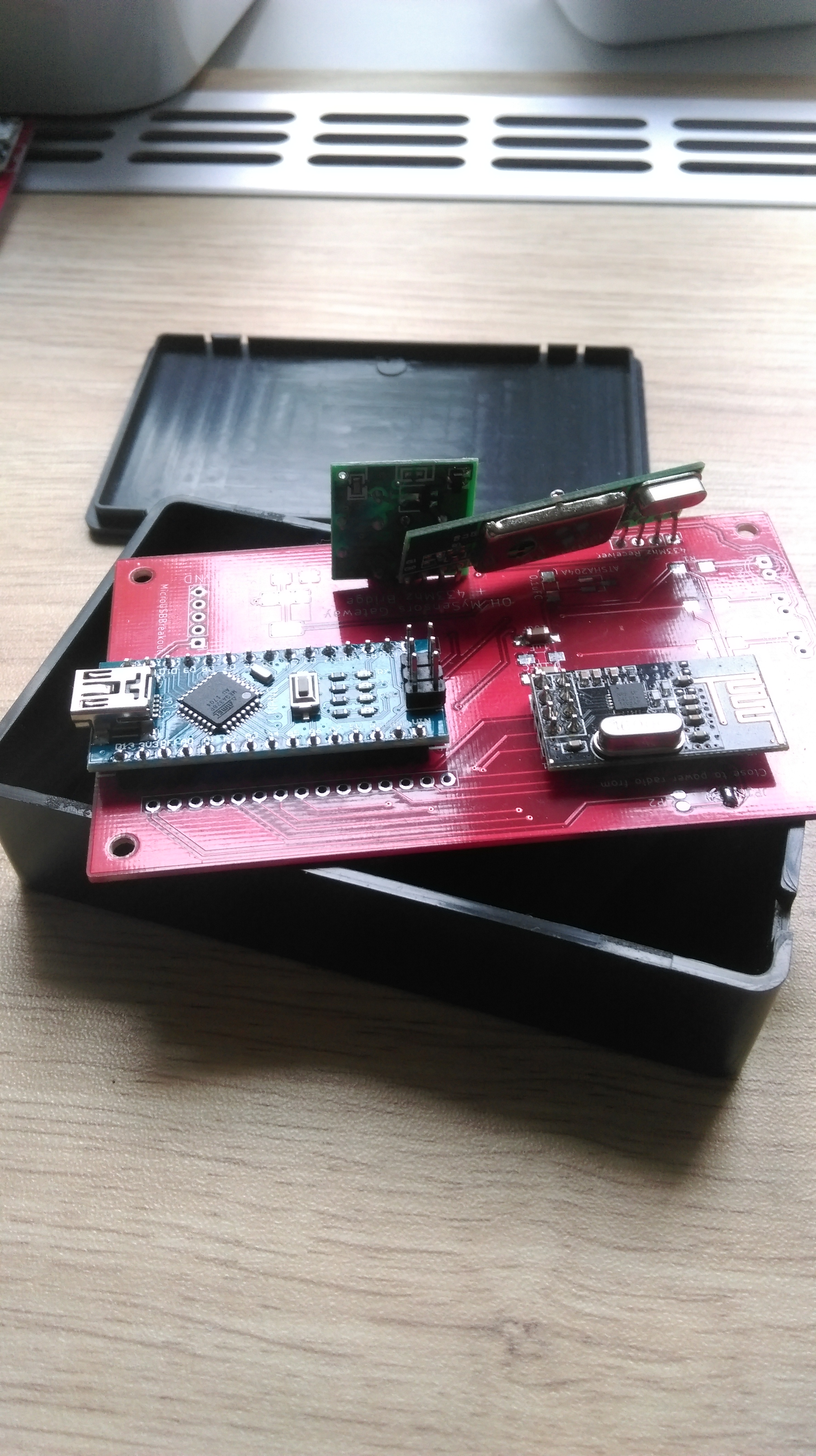
The third version I will be building is a separate gateway that connect the 433Mhz devices to the MySensors gateway. For that I'll be using an arduino nano, a normal NRF24L01 and a 433 receiver + sender. This more or less matches the separate gateway I have already published here.
PS Its done. Here are some pictures of it. The 433Mhz receiver I used are a little bigger than expected so they don't fit perfectly but it's still working. The whole thing is powered by the usb connection of the arduino nano.
I also uploaded new code that the gateway uses. It simply created 2 sensors of the "text" kind. One is the receiver the other one the sender. This way the gateway can decide what to do with the messages and you don't have to change your node's code once you want to integrate new devices.

Case
If you want to build a more advanced gateway it is most likely that you want to use a dedicated case to secure the components against dirt and accidental damage. I have been using this case. The pcb is designed to perfectly fit in there and also has screw holes that match the standoffs in the case. You only need to drill some holes in the cases side for the connections (antenna, serial connection and power + possibly leds).
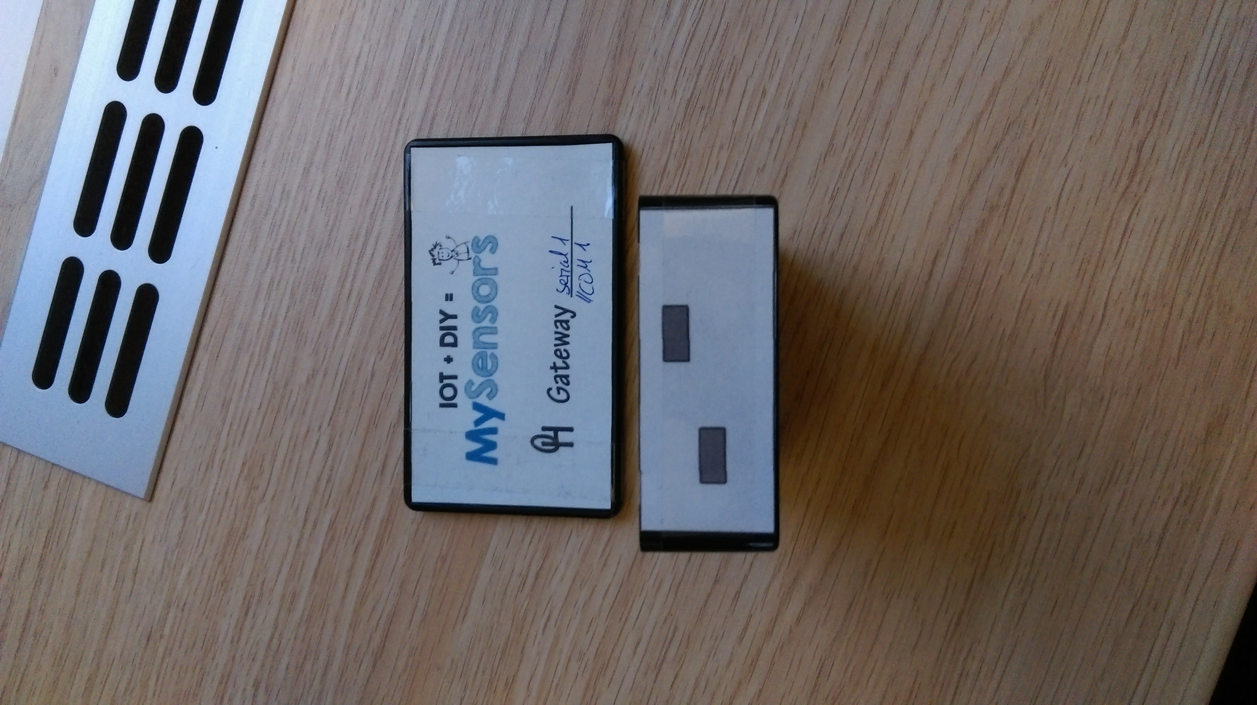
I created some drilling templates / stickers for the box using SketchUp. The original SketchUp file and the pdf export can also be found here in the files section. There are 2 versions: one with and one without all the sizes. The templates contain 4 parts: left = led/antenna side, center = NodeMCU side, right = Arduino Nano side, bottom = top of the case.

PS
The gateway in my pictures (especially the leds) is looking a little rough because this is my demo case. It already had holes in slightly different positions so I couldn't get them exactly where I want them to. I will also upload pictures from my next build though. That one will be from scratch so it should look much nicer.

