@Nca78 Do you tested this board, if yes, did it work? And which CS capacitors did you use?
This board allows you to transform a 433MHz "VHOME" remote control switch into a MySensors switch. This will complement my Livolo switches The base switch is available at the link below. The seller always changes the prices so I cannot link to a specific model, but there's always a set of switches (1, 2, 3 buttons) below 10$.
https://www.aliexpress.com/store/group/Switch-shape-remote-control/1112973_510025631.html
This version is for 1 or 3 buttons switches, I will make a version later for the 2 buttons switch. I'm using a TTP224 to manage the 3 touch buttons with only one chip, as the power consumption is nearly the same as a TTP223 (that manages only 1 button)
WARNING: I have unfortunately not yet received the PCBs, so please wait a few days before making PCB orders so I can confirm it's running as expected...
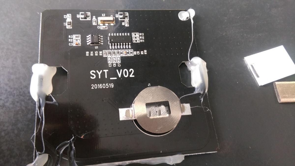
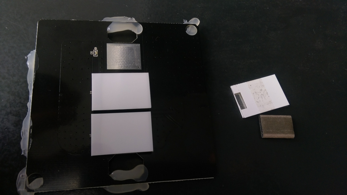
Taking the existing switch appart
The original PCB is glued to the switch so you have to remove it with a screwdriver, be careful not to ruin the paint on the front glass with it
 We will keep the CR2032 holder and reuse it on our PCB so you can unsolder it.
On the other side, the "buttons" or at least their covers are made of a bit of conductive foam that pushes the white plastic layer on the surface of the glass. It's pretty efficient at making the led light even on the button, while thanks to the conductive foam it provides a good sensitivity for the touch buttons. Good reasons to keep them and reuse them on our board !

Assembly process
I think information on board is clear enough. You have additional information in the schema that you can open in free version of Eagle. There's plenty of space on the board so you can solder in nearly every order you want.
Only recommendations I have are :
- use at least 2*100µF for reserve capacitors
- as those are a bit far from the radio module, I did put a capacitor footprint next to the radio in addition to the 10µF filter capacitor. Don't overlook it, and in the worst case put only one 100µF capa near the button cell and the other one next to the radio
- use a 1MHz bootloader with no or 1.8V BOD. In theory 8MHz should allow to save battery with faster wake up time, but my practical experience is this is quickly wasted as soon as you have a little transmission difficulty and the ATMega has to stay awake longer during resend. 1MHz frequency will also keep maximum power consumption (AtMega + radio) below 15mA that is the maximum peak current we should draw from a CR2032 cell.
Script for this board
Pins used for buttons and led
| Button N# | Touch button pin | Green led pin | Red led pin |
|---|---|---|---|
| 1 | 2 (INT0) | D5 | D6 |
| 2 | A2 | D4 | D7 |
| 3 | 3 (INT1) | A5 | A4 |
Pin Change Interrupt
As you can guess, the external interrupts will not allows us to use the middle button on A2 pin, so we have to use the Pin Change interrupts to manage this board. Unfortunately this is not managed directly by MySensors so we have to use a few tricks. I've not had time to look into this at the moment so I can't supply a script at the moment, but it's already been done by other MySensors uses so it won't take very long :)


 Battery powered glass touch switch