Heat controller
This is a project that have been in the planning stages for the last couple of years, as I wanted to "modernize" our floor heating system, from an electromechanical switch to something MySensorized.
The old thermostat consists of a electrically operated valve, and a sensor that contains a relay, the temperature is controlled by a small screw on top, and it is hard to hit the right values as just a notch to the wrong side it is either too cold, or too hot.
One of the things that had kept me back, was actually the building phase, as soon as I have to build a birdsnest of something (like using regular arduino, and add wires to connect the radio etc.) I tend to keep my self from doing it, it's too much hassle and I have too many projects going on :)
I had an early prototype of the sensebender gateway laying in the parts bin, so I used that to build my setup.. (probably way overkill, but it has the radio connector LDO regulator etc. in place for the radio). One of the added advantages of using the gateway (SAMD based) is that it has an RTC onboard, which makes timing a lot easier, I use the RTC for determining when I report temperatures, and also in the statemachine when I have states that run for a specific time.
Parts used
The following hardware parts is used:
- 1 x 2 channel solid state relay
- 4 x DS18B20
Relays are connected to MYSX_D3_INT and MYSX_D4_INT, while onewire bus is connected to MYSX_A1. I have chosen to use all 3 pins on the DS1820's, so I have constant power to them.
Setup
The DS1820 sensors are attahced to various points in my heating system,
- Floor heating loop
- Hot water inlet from heating supplier
- Return water out to the heating supplier
- Hot water for showers etc.
The two relays are used to control the valve for letting hot water into the loop, and for controlling the circulation pump.
Operation
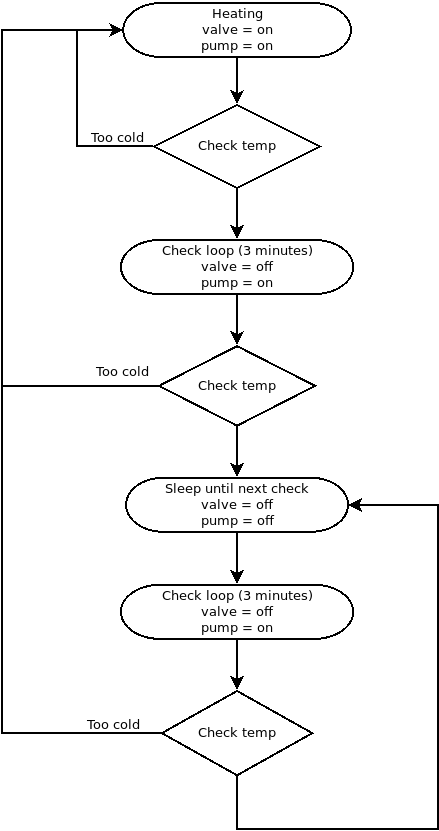
The enclosed sketch implements a simple statemachine, with 6 states:
- Heating
- Heats up the floor loop, when entering this state both pump and valve is turned on, and the state is running until the temperature in the floor loop is above the target temperature set (with an added hysterisis).
- If the floor loop temperature exceeds the temperature set enter Heat check state
- Heat check
- This state turns off the valve, but keeps the pump on for a couple of minutes (currently 3 minutes). After this time a measurement is taken of the floor loop, if temperature is above target, then we go to the Cooling state, otherwise return to the Heating state.
- Cooling
- Starts by turning off both pump and valve, and then waits for 30 minutes before entering Check floor temperature
- Check floor temperature
- turns on circulation pump for 3 minutes and then checks temperature of the loop, if the temperature is above the target temperature we return to the Cooling state above, if below then go to the Heating state
- Fetching hot water
- This is a convenience state, sometimes (specially in the summer where we have the heating turned off) it takes some time to get hot water into the house from the supplier. This state turns on the valve to get hot water into the building.
- Stays in this state until the target inlet temperature is met, after which it returns either to summer or cooling states
- Summer
- Turning the system "off"

All of the above is now controlled via domoticz, measurement data is also stored in an influx database, so I can create nice graphs with grafana