@terxw okey, thanks for reporting back !! Let me know if there is something else. This is a 0.5v so I'm open for improvements.
This logger sends serial (debug) communication to Bluetooth or writes it to an SD-Card
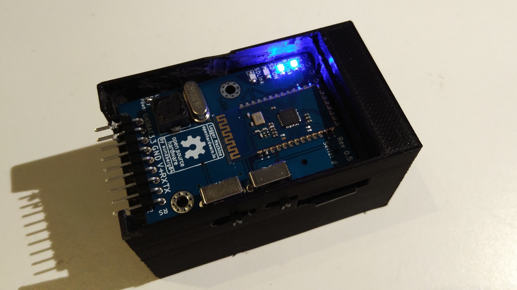
This logger includes some different features when you need to log your devices. First is that you have both a Bluetooth and an SD card output. In a situation where you wish to log for a long period of time, you can log the messages to a sd-card and read them later on in your computer. On the other hand, if you have a remote node or just want to make a quick look at what happens you can use the Bluetooth output and watch real-time on your smartphone/tablet/computer without having to connect your Computer > USB-ftdi adapter > node. Another great thing is this logger can handle all common voltage levels for microcontrollers in the MySensors or Arduino world.
Why?
When my home automation project grew to more than a few nodes I had to think about new ways to debug since running around with a computer/ftdi adapter wasn’t practical anymore.
- Remote nodes – I can't drag a computer with USB/FTDI adapter out into the garden and I don’t want to remove the node from its current position since that might give me false debug output.
- Nodes with intermittent problems – I have a few nodes that work well most of the time, but with a small change in the network I can get a node malfunctioning... To be able to catch these debug logs when the note fails I had to be able to leave the logger by the node.
- If I connect my computer to debug the GW I had no chance to simultaneously debug my repeaters or the node itself.
Neither SD-card logging or Bluetooth logging is new but I wanted a combined logger that can do more so this made me create this light and portable logger.
What?
Input
All Serial communication that uses TTL logic levels from 2.2v to 5v (including 3.3v) should work. Up to 115200 baud rate should not be a problem reading. Any MySensors or other Arduino/ESP/NRF node with access to TX pin should be able to attach to the input of this logger.
Output 1 - Bluetooth (Short-term logging)
Bluetooth is mostly used for short-term logging. By Using your smartphone, tablet or computer with Bluetooth and a software to read Serial communication you have a portable solution for debugging any home-automation node or other devices.
Depending on where you have ordered your Bluetooth chip, baud rate and other settings may have to be changed.
By setting the selector to BT you will enable the Bluetooth part.
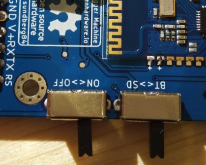
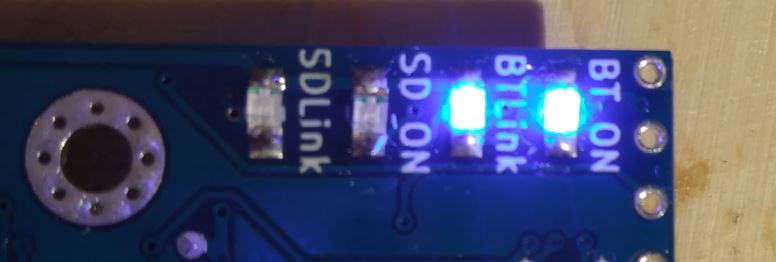
BT ON (led) will light up and BT Link will flash when unconnected.
Depending on the app, you might have to pair the logger Bluetooth module with your phone/tablet/computer. Any 4 digit pair password is found where you bought the module or some google search. HC-05 has 1234 as default.
Connect TX (On the node you wish to log from) to RX (on the logger). Also, connect GND - GND (node - logger).
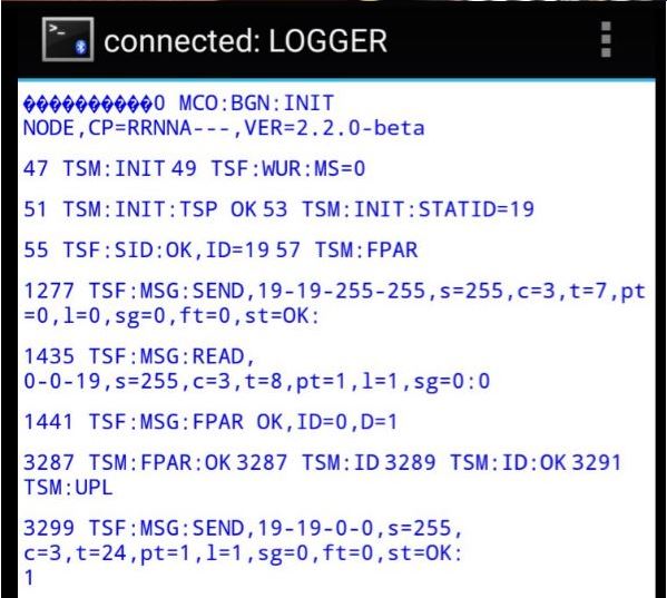
Now it is time you fire up your favourite Bluetooth serial app. Search "Bluetooth Serial Terminal" in app/play-store if you haven't got any installed before. Connect to the paired logger and enjoy the stream of serial debug messages.
Once connected the BT Link (led) will be a solid light.
Output 2 - SD Card (Long-term logging)
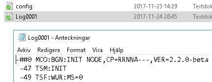
SD-card logging is mostly used for long-term logging. The sd-card will write any incoming data to a log file which can be reviewed later on your computer.
Before connecting a node for logging to the SD-card, make sure you have the right baud-rate set compared to the node. In normal cases, MySensors uses 115200. See below for installation instructions on the firmware. On the sd-card, you need to have a config file (or the logger will create one for you).
Make sure this config file is set to 115200 (or your nodes baudrate) and ignoreRX = 1 like below:
115200,26,3,0,1,1,1
baud,escape,esc#,mode,verb,echo,ignoreRX
Make sure you have the SD-card inserted. By setting the selector to SD you will enable the SD-card logging. If you insert the SD card while the logger is powered, reboot the logger to initialize the sd-card.

Connect TX (On the node you wish to log from) to RX (on the logger). Also, connect GND - GND (node - logger). SD ON (led) will light up
SD Link will flash when writing data to the SD-card
Power
You can power the logger in different ways as long as the voltage stays between 1v to 5v (depending on VCC pin!) See below for most common uses.
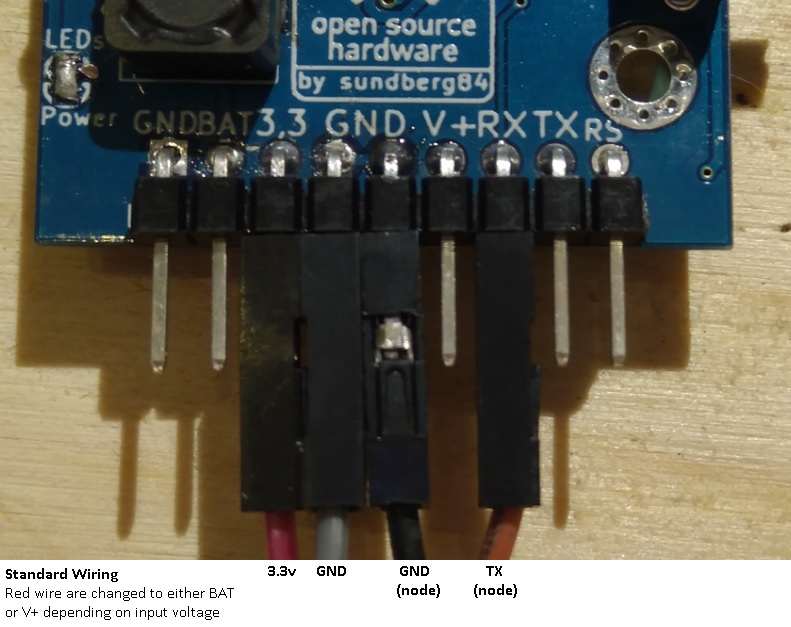
Regulated power (3.3 pin) The logger runs at 3.3v so if you have this regulated power just connect it to the pin marked "3.3". The on/off pin on the logger will not affect this pin so a connected 3.3v will turn the logger on.
3.3 to 6v (V+ Pin) If you use a wall plug or phone charger (5v) use the V+ pin to power the node. On board, you have a voltage regulator that can handle everything up to 6v and output 3.3v to the logger.
Battery (BAT Pin) The logger is designed to be able to run for some time on 2xAA (see the attached 3d-printable box where you have a slot for this). Connect your batteries to BAT/GND and this will go through an NCP1402 and output 3.3v to the logger.
Parasite mode If you have a node with access to a pin with any of the above voltages you can easily parasite power from the node to power the logger. Just remember if you have a battery-powered node it will shorten the life of those batteries! Also, note that in some cases you will create noise that might interfere with the radio on the node you wish to log - making the logging faulty.
You can also parasite power from the logger itself - if you provide either power to BAT or V+ you will have a regulated 3.3v on the 3.3pin which can be used to power a node.
- What about the TTL Logic level voltages? You can connect any node you wish to log that is running on 2.2 to 5v. The node decides the voltage on the logic level voltage and the logger is designed to be able to read everything from 2.2 to 6v. Anything below 2.2v might cause a floating RX/TX line and the logger might not be able to read the data correctly.
Jumpers
- SD/BT: This changes between SD logging or BT logging.
- ON/OFF: This will switch BAT/GND but not affect if you connect a power source to VCC or 3.3v
- Power LED: To save some power when using batteries you can un-solder these leds.
Boxes/Enclosures
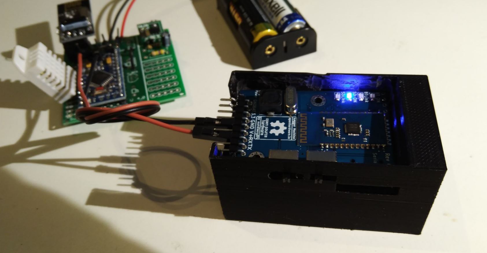
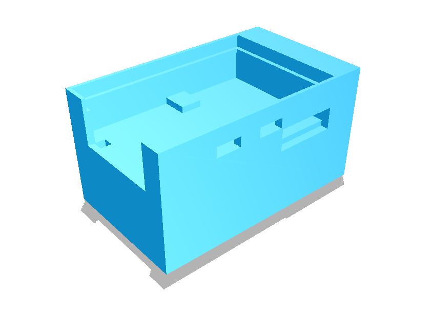
Attached to the project is a 3d-printable case. On the back, you have room for a standard 2xAA plastic holder and on the front, you can screw the logger to the case. This to create a nice looking and easy to use logger-node.
(NOT TESTED)!
Build and Installation
Attached to the project is a checklist for building this logger. The first step is of course to buy everything needed (including the PCB) from the BOM.
To make it a bit easier I have created a BOM Description where you can find all items needed and where to solder them. Once soldered there are 5 different test-points to check (see checklist for more info).
Bootloader
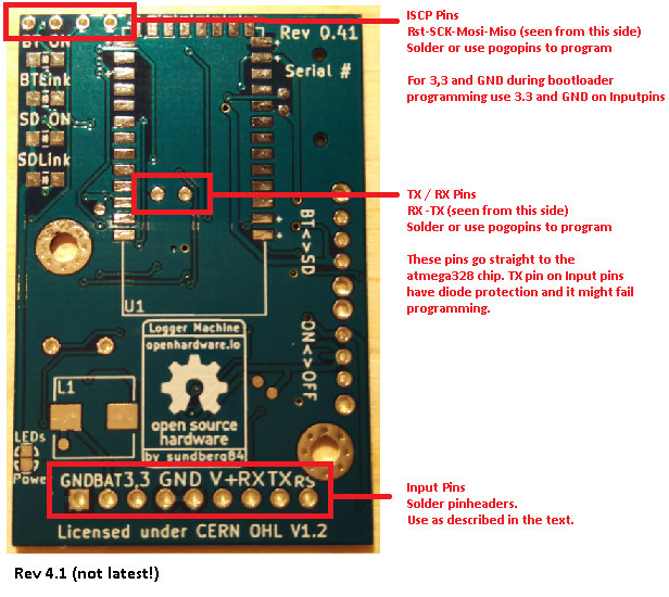
I recommend using some Optibot 16mhz external crystal with NO or 1,8v BOD. I have tried both Optibot and GertSanders Optibot bases bootloader with great success. Connect 3.3 and GND on the "Input pins" and rest of the ISCP pins on the "ISCP Pins" in the upper left corner (see below).
Firmware
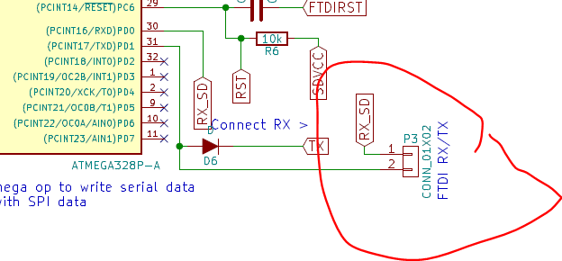
Next step is to download and upload the Firmware from OPENLOG using the standard FTDI-Usb device from the Arduino IDE. Connect GND, 3,3 and RST on the "Inputpins" (see above) and RX/TX on the pins close to the atmega328p chip.
By default, I recommend using openlog firmware to handle sd-card logging. There are three different firmware and I find the _light version best. After uploading the firmware adding a config file to the sd-card tells the Microcontroller all the necessary settings. This config file can be found here as well but will be created automatically on the sd-card if not found when booting.
Make sure this config file is set to 115200 (or your nodes baudrate) and ignoreRX = 1 like below:
115200,26,3,0,1,1,1
baud,escape,esc#,mode,verb,echo,ignoreRX
Openlog firmware is released under Creative Commons Share-alike 4.0 International and all rights belong to Sparkfun. I have not made any changes to this firmware (because it's so good) and will not release an own version. All credits for this excellent work should go to Sparkfun (which also sells a SD-card logger for which this firmware is created)
BT Settings
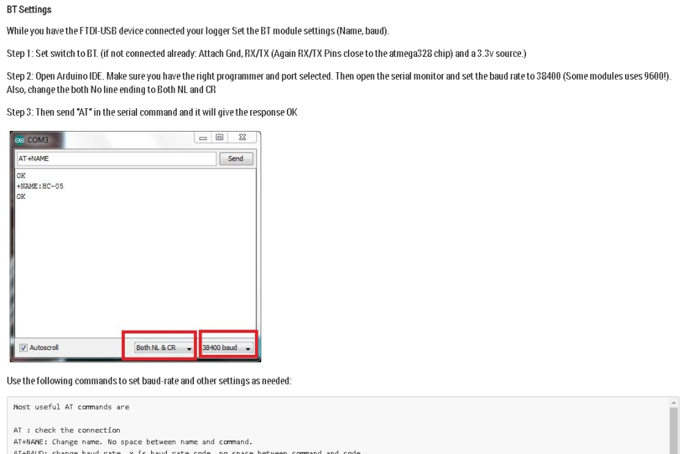
To be able to set the BT module settings (Name, baud), connect the ftdi adapter to the logger.
Step 1: Set switch to BT. (if not connected already: Attach Gnd, RX/TX and a 3.3v stable power source to 3.3)
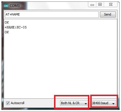
Step 2: Open Arduino IDE. Make sure you have the right programmer and port selected. Then open the serial monitor and set the baud rate to 38400 or whatever last setting you set the logger to (Some new modules uses 9600!). Also, change the both No line ending to Both NL and CR
Step 3: Then send "AT" in the serial command and it will give the response OK
Use the following commands to set baud-rate and other settings as needed:
Most useful AT commands are

AT : check the connection
AT+NAME: Change name. No space between name and command.
AT+BAUD: change baud rate, x is baud rate code, no space between command and code.
AT+PIN: change pin, xxxx is the pin, again, no space.
AT+VERSION

1 set to 1200bps
2 set to 2400bps
3 set to 4800bps
4 set to 9600bps (Default)
5 set to 19200bps
6 set to 38400bps
7 set to 57600bps
8 set to 115200bps

So sending AT+BAUD4 will set the baud rate to 9600.
The commands may vary depending on which BT module you got! Check here for more detailed info!
Revision Changes
Rev 0.5 - First public release
A device listening for Serial TTL communication and either write this to an SD card or sends it via Bluetooth.
Can be operated on battery, 3.3v or 5v
Can handle all TTL levels from 2.2v to 5v
Known issue: Hard to make contact to BT serial for changing baudrate, name, pin and other settings through serial communication due to diodes and TTL logic level conversion. Workaround: Solder pins/wires directly to RX/TX on BT module.
I want it!
Order 10pcs PCB: Openhardware.io (Recommended!) and support me and MySensors!
Download from this page to get KiCad and Gerber files and upload to your favourite PCB house!
If you want PCBs with a faster shipping time or fewer pieces you can order from me on Ebay.
If you want to order a complete working module - send me a PM!
QnA/FAQ
- This will be filled up with questions as we go!
Suggestions for next revision
- Input protection (Diode clamping)
- Relocate BLE module so antenna is free of copper!
- MysX as input.



 op
op