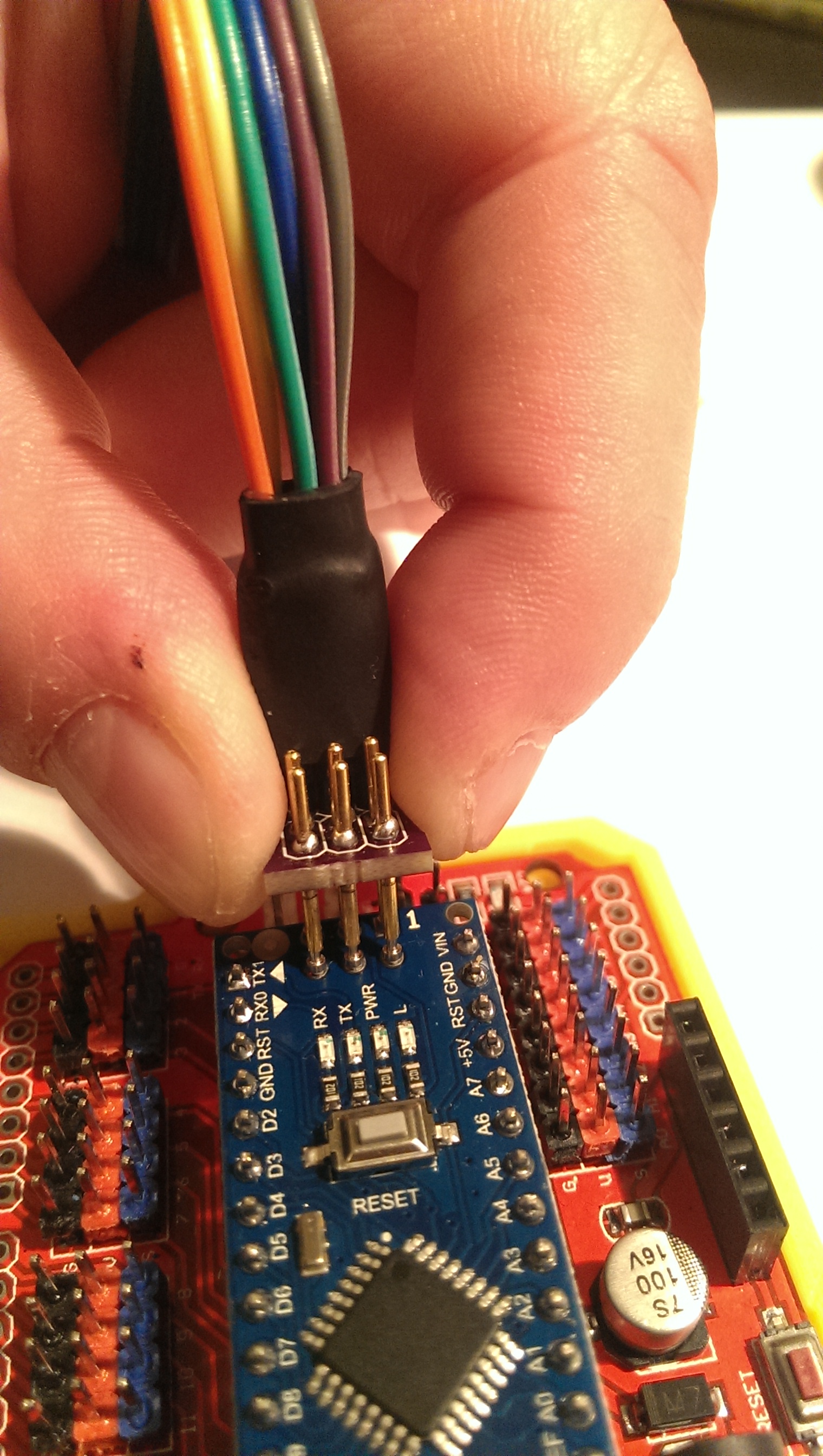
PogoPin adapter for ICSP and FTDI (Aduino programming)
When programming microcontrollers (especially with the Arduino IDE), the most common connectors are the 6-pin FTDI / UART (via USB serial) and the 2x3 pin ICSP connector to burn bootloaders to AVR chips.
A self-designed PCB and most third-party PCBs will either provide pin holes for the FTDI or the ISCP interface to upload sketches or burn the bootloader. However, after the initial software development and testing phase of the sketch, these connections are hardly ever used again once the sensor node is up and running.
So, I usually don't want to solder male pin headers to the ICSP pin holes on the PCB, as I know I will never ever use them again after the initial bootloader upload. Unfrotunately, using the male header pins of the USB interface with the unsoldered pin holes in the PCB is a messy story and no matther how you tilt the connector press the pins agains the unsoldered holes, it is almost impossible to keep a stead connection of all six pins with the PCB.
PogoPins are the solution to this issue: They remove the need to solder pin headers to those connectors, while still allowing a good electrical connection during upload. PogoPins are spring-loaded pins with a thick head and ~3mm spring load. This means that you can use a connector with PogoPins and simply press it agains unsoldered pin holes, while still maintaining a good electrical connection. You don't even need to hold the pins exactly perpendicular to the PCB, as the springs will correct that and still apply enough pressure on the holes to let the signals flow to the PCB.

This project provides two trivial interface PCBs for a 1x6 pin (FTDI) and a 2x3 pin (ICSP) connection.
The PCBs can also be ordered at OSHPart for very little money:
- 1x6 pin FTDI version: https://oshpark.com/shared_projects/nUF6Am0T
- 2x3 pin ICSP version: https://oshpark.com/shared_projects/nbNVd7UW
| Qty | Value | Device | Package | Parts | Description | MF | MPN | Aliexpress or Ebay link |
|---|---|---|---|---|---|---|---|---|
| 6 | PogoPins | PogoPins, 1mm diameter, 1.3mm head diameter | https://www.aliexpress.com/item/100pcs-Gold-Plated-Spring-Test-Probe-Pogo-Pin-1-3mm-Conical-Head-1-0mm-Thimble-For/32804776498.html |
| Name | Size | # Downloads |
|---|---|---|
| PogoPins_FTDI.brd | 25.28 kB | 1848 |
| PogoPins_FTDI.sch | 31.94 kB | 1834 |
| PogoPins_ICSP.brd | 25.5 kB | 1847 |
| PogoPins_ICSP.sch | 20.87 kB | 1399 |