

I buy them on Aliexpress:
https://www.aliexpress.com/wholesale?catId=0&initiative_id=SB_20180706102504&SearchText=HTTM
If you apply hot air it is easy to take off the white "double sided tape" and the plastic.
The project is in development. You can see the status of this and other nodes from my work panel (In Spanish)
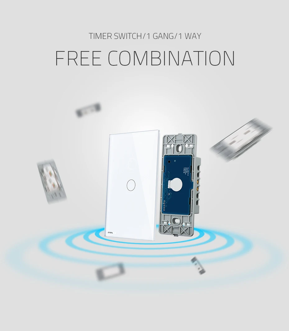
This circuit is a touch switch that replaces the wall switches and allows you to control the lighting (on and off, in the future I want to make another plate to regulate the brightness), uses two PCBs, the first one is black and includes the microcontroller, antenna, etc., the second PCB is red and includes the AC part, power supply, relays, etc.
Features:
Requirements:
** Project status (OK / PENDING TO TEST / ERROR): **
Notes:
Este circuito se trata de un interruptor táctil que sustituye los interruptores de pared y que permite controlar la iluminación (encendido y apagado, en el futuro quiero hacer otra placa para regular el brillo), utiliza dos PCB, el primero es de color negro e incluye el microcontrolador, antena, etc., el segundo PCB es de color rojo e incluye la parte AC, fuente de alimentación, relés, etc.
Características:
Requisitos:
Estado del proyecto (OK / PENDIENTE DE PROBAR / ERRORES):
Notas:
2018/XX
+ TOUCH SWITCH BOARD V2.2:
    - Improve logos and change position.

+ RELAY SWITCH BOARD V1.2:
    - Change AC connectors by ones at an angle (and modify the plastic shell with the new design)
2017/12
+ TOUCH SWITCH BOARD V2.1:
    - Move programming connector to the inside of the board, it was colliding with the plastic housing.
    - Modify the pinout of the RGB LED, the green and blue colors of the reverse.
    - Add text that identifies the functionality of the board.

+ RELAY SWITCH BOARD V1.1:
    - Replace SSR relay with 5A mechanical relays.
    - Add text that identifies the functionality of the board.
2017/10 INITIAL VERSION
+ TOUCH SWITCH BOARD V2.0.
+ RELAY SWITCH BOARD V1.0.

 m8U0RNT_lW0oZAr9my3wYKg
 Wireless Touch Switch: Relay Model - (For Livolo crystals)

")