

@nca78 I don't use ATAES132A. I put it in just in case I wanted to invest some more time using it.
I now just use SimpleEncryption, it's secure enough for my purpose atm.
(since the area I live in uses KAKU a lot, an insecure 433MHz lightswitch, I don't think anyone would be bothered to hack my temperature sensors. I found 163 433Mhz devices when I left domoticz logging for a couple of days.)
NRF52 Wall-Node (3 AAA)
License:
Attribution-ShareAlike (CC-BY-SA)
Created:
7 years ago
Updated:
5 years ago
Views:
57773
14 Like
6 Collect
2 Comments
135 Download (10.2 MB)
_> 8-9-2018 - node has been active for a couple of days now, no breakdowns etc. I consider this one final, if there are suggestions/questions, please let me know. _
_ 13-10-2018; Found a little mistake in the sketch, don't mind the debug entries I use;),
21-8-2018; might have found a small mistake that makes the LDO I use not functioning properly,
26-8-2018; So far it worked!
- fixed my mistake with the LDO by soldering a wire to connect the enable pin. I'll upload corrected Geber files soon.
- Added sketches, they work but don't know that the sleep current is atm.
28-8-2018; Uploaded new Gerber files
29-8-2018; Uploaded sketch, since my multimeter only does mA, I can confirm it sleeps at around 00.01 mA, when woken up, it rises to 17 mA.
29-8-2018; Hmz, upload of the sketch went wrong... uploaded again.
5-9-2018; Drilled the holes and assembled the endproduct, Uploaded last sketch and last updated Gerber files.
8-9-2018; Tilted the PIR to have a wider field of sight. => also tested the range with this gateway. I got about 15 meters, including 3 single brick walls and an outer brick wall (2 layers incl insulation). So I'm pretty content with the range. When this would be too little, I can fall back to a couple of repeater-nodes.
_
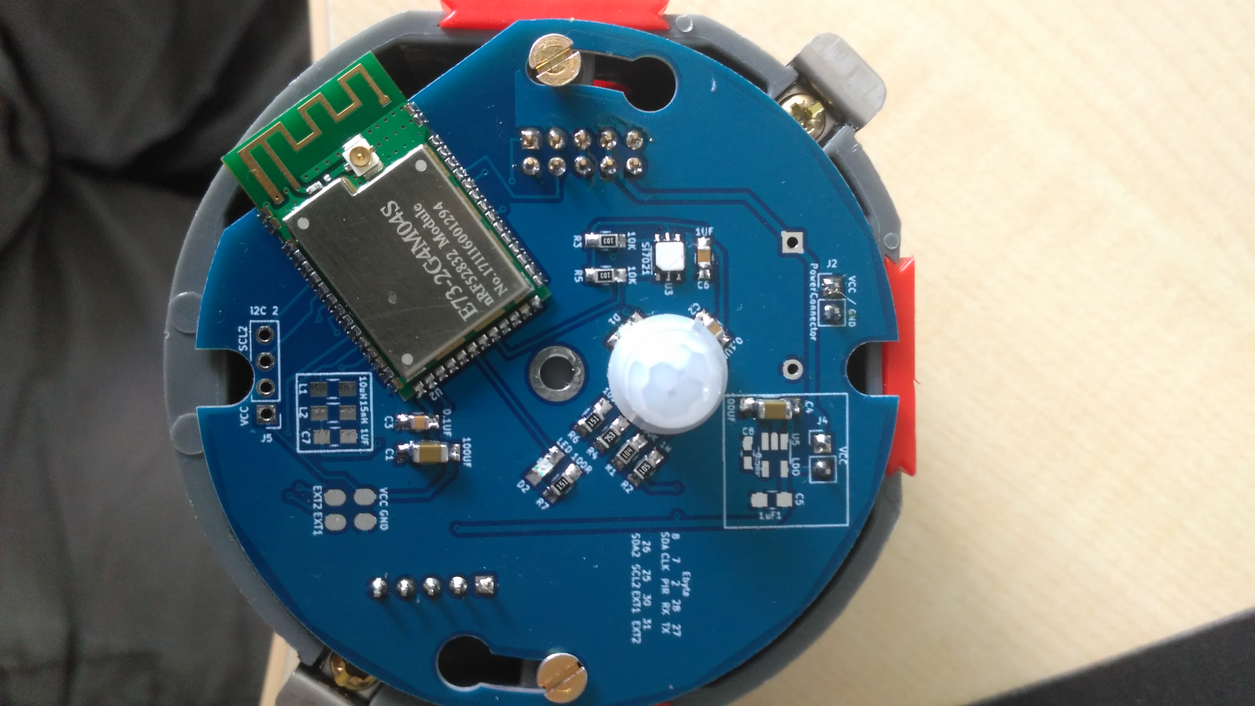
Battery-Powered NRF52-Node, with PIR + RH/T for building into a wall socket.
(it has the same dimensions as the AC powered node )
I started with the Idea of building a wall mounted socked in every room in my house, one I could place next to every light switch or electrical outlet. I made some progress over the months, where I first made an inwall node that was made to be built with a local store outlet-front LINK to gamma.nl => PCB that fitted into that outlet.
Since the new house is built with JUNG outlets I redesigned the PCB so it fits with the JUNG AS500 outlet series.
So, the introduction is over, let's talk about the design.
It is a node powered by 3 AAA Batteries, but if needed can be fed from another 3 up to 5V input. The PCB is made to replace the steel bracket so it fits right in as a replacement and you only need to drill a small hole for the PIR-cap and the temperature sensor.
The Temperature-sensor is a SI7021.
As for a PIR-sensor, I took the AM612
PCB: as mentioned, the PCB is made to be a replacement for the metal bracket for the JUNG AS500 Blind front. As this metal bracket is 1mm thick, I also recommend using this thickness for your PCB as well. Around the screw holes, I made some copper plating to make the PCB more sturdy. The JUNG front can also be bought without the metal bracket: Fabnr: A594-0PLWW | EAN: 4011377014671 -- Since I cannot upload Kicad Files here, I shared the Kicad Inlay via: https://github.com/Omemanti/KiCAD/blob/master/Footprints/Other.pretty/JUNG_AS500_INLAY.kicad_mod
Untested: I was scouring the forum and found that there might be an implementation of an ATaes132a, so I took the liberty to place it in there, even though I might not even use it. Also, hope it is connected well.

