BEEP - Measurement system
This is a repo containing the files to create the open source hardware for the Beep measurement system.
Measurement system parts
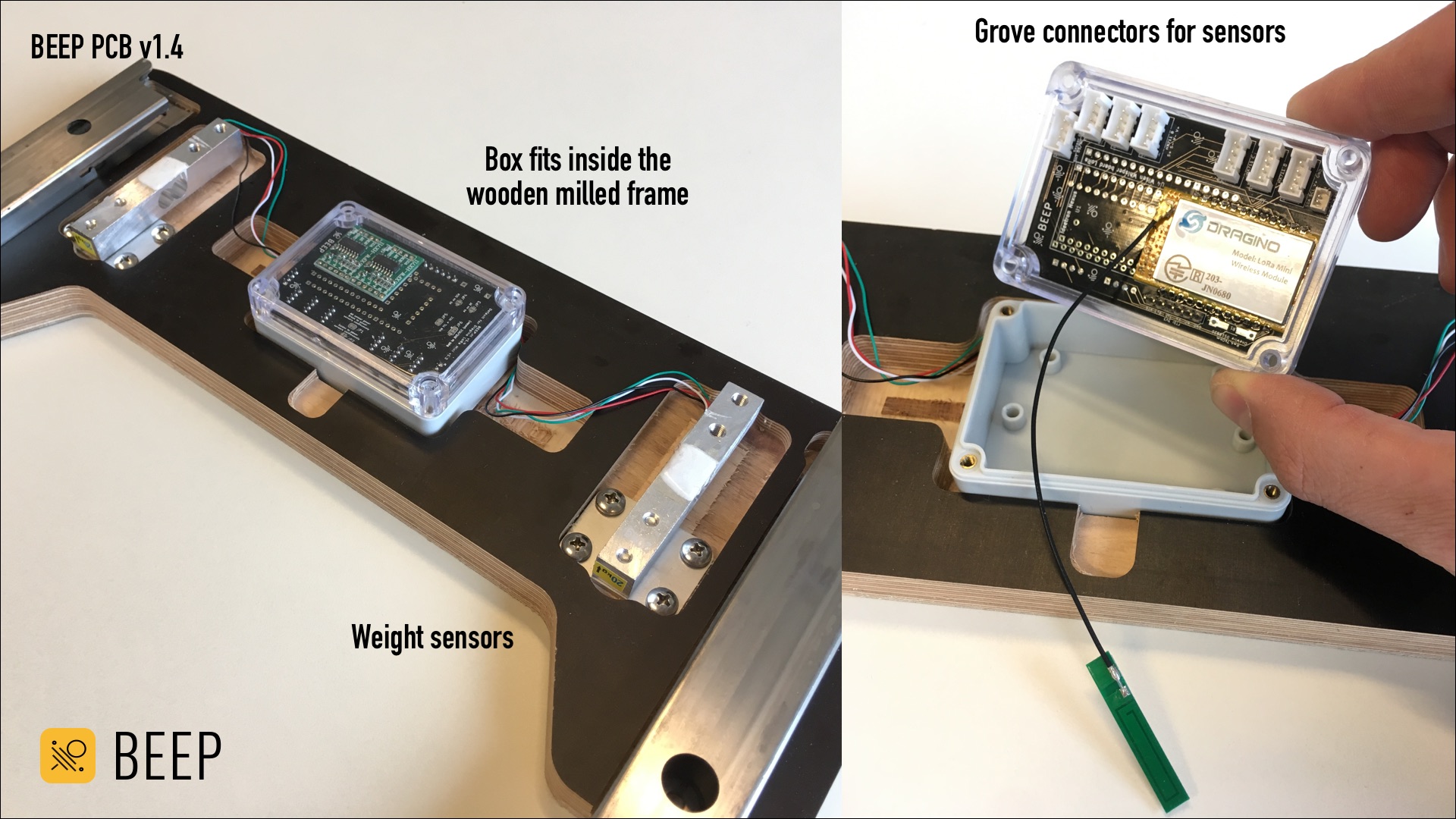
The measurement system casing is designed as both an electonics/sensor housing, as well as a weighing frame. The outer casing is assembled in four pieces (2 tops, 2 bottoms) out of 18mm thick plate 'Betonplex' (glued multiplex with water resistant top and bottom layer). The wooden top and bottom are connected together by the 2 weight sensor (aluminium) blocks, held in place by 2 weight sensor brackets each. The left and right part are held together with 2 stainless steel tubes, that are screwed on the wood. At one side tightly, using wood parkers, at the other side loosely, using m4 bolts that go inside the inserts. By this connection, the total size of the frame is adjustable for different types of hives.
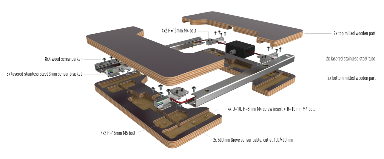
Frame
The folder 'frame' contains two folders: wood and stainless steel.
Wood
The 2D drawings in both Illustrator format and DXF (required by most milling parties).
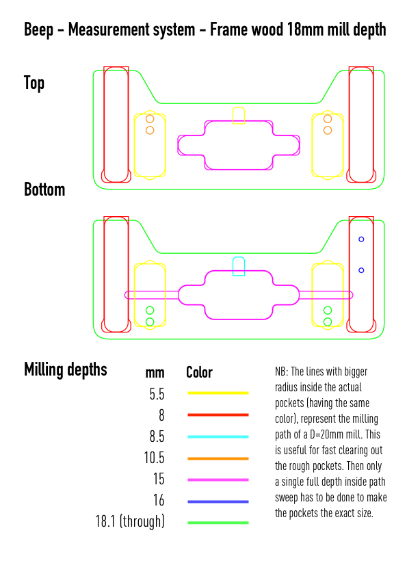
This is a picture of the milling software, with which we mill 42 pieces (21 tops, 21 bottoms) out of an 2440 x 1220 x 18 mm Betonplex.
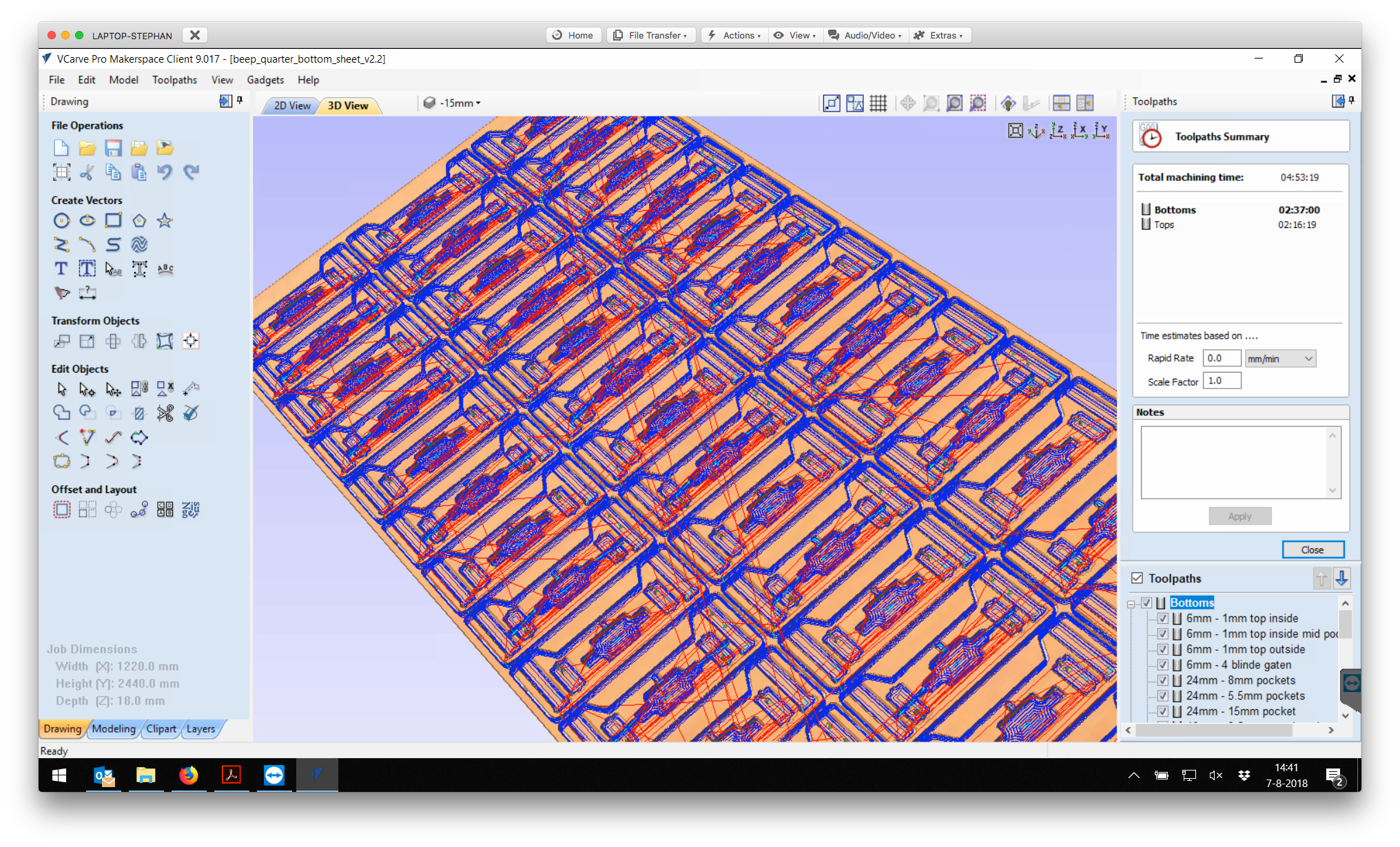
Stainless steel
The 3D and 2D drawings of the stainless steel tube, and the sensor bracket are in this folder. They can be ordered at companies lasering steel.
Electronics
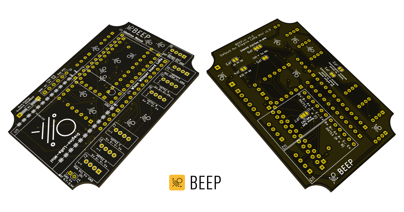
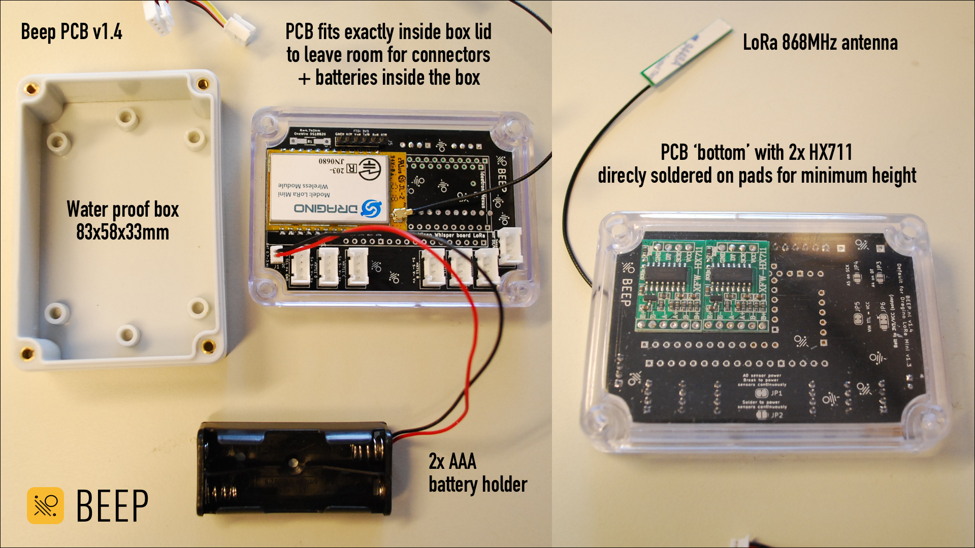
The electronics of the measurement system are bundled together on the Beep PCB, which connects an Arduino, a LoRa (wireless network) chip and the sensors via Grove connectors together.
The folder 'electronics' contains two folders: gerber and kicad.
With the Gerber files, you can directly order a PCB. It contains all files required for the manufacturing of the PCB.
With the Kicad files, you can edit the PCB and it's components in the open source PCB creation software Kicad (http://kicad-pcb.org/).
Schematic
NB: There is an error in the PCB, the one wire temperature sensor DS18b20 cannot work on analog port A7 (the A6 and A7 IO pins can only be used as analog pins, not as digital IO). So you have to use A4, or A5 to connect one wire sensor(s) to. So you also have to add the 4k7 resistor between V+ and the one wire data pin yourself, since the resistor on the PCB is connected to V+ and A7.
The schematic can be found in the PDF (https://github.com/beepnl/measurement-system/raw/master/electronics/Beep-pcb-v1.4-schematic.pdf)
PCB
Assembly
Firmware
In the 'firmware' folder, the ultra low power Arduino code is shared to use with the PCB and complete the measurement system.
Place the folder 'Beep-low-power' inside your Arduino folder and set up your own LoRa connection details to send the data. Send an e-mail to pim@beep.nl, to add your Measurement system Device EUI to your Beep app account and receive it's measurements in the app.
Improvements
If you have improvements, or ideas for creating a better frame, please send an e-mail to pim@beep.nl explaining your thoughts. Or just fork this repo, and do a pull request with you adjustments, or additions.
