Overview
We use home assistant to automate lights and media at home, and I finally got around to build a fairly robust bed occupancy detector for our home. When searching for products in the market all of them turned out to be very expensive but this ended up fairly cheap.
It has gone through a number of iterations but I will only present the final version here which only sends update whenever it detects a change in weight on the bed, as opposed to a continuous stream of weight measurements.
The basic setup is two FSRs, which are first fed through voltage dividers and then through an op amp to find trigger signals. Those trigger signals are then wired to an ESP8266 which detects changes through interrupts. When an interrupt is triggered it reads the current state and sends an MQTT message to a specified MQTT topic.
The home assistant has two binary sensors setup which are based on this MQTT topic which then triggers miscellaneous scenes.
Prerequisites
- A working Home Assistant.
- A working MQTT server.
- Some knowledge about electronics.
- Some knowledge in how to configure Home Assistant.
Hardware
The main parts that I use are
- ESP8266
- 2 x Interlink 408 FSRs
- LM358 Dual Op Amp
The total cost would be in the range of $50.
Those are all interchangeable to other similar parts, so don't feel limited to the exact parts I use.
Sensor Construction
The sensor consists of a voltage divider, a comparator, and the ESP8266. I will go through each in part explaining them.

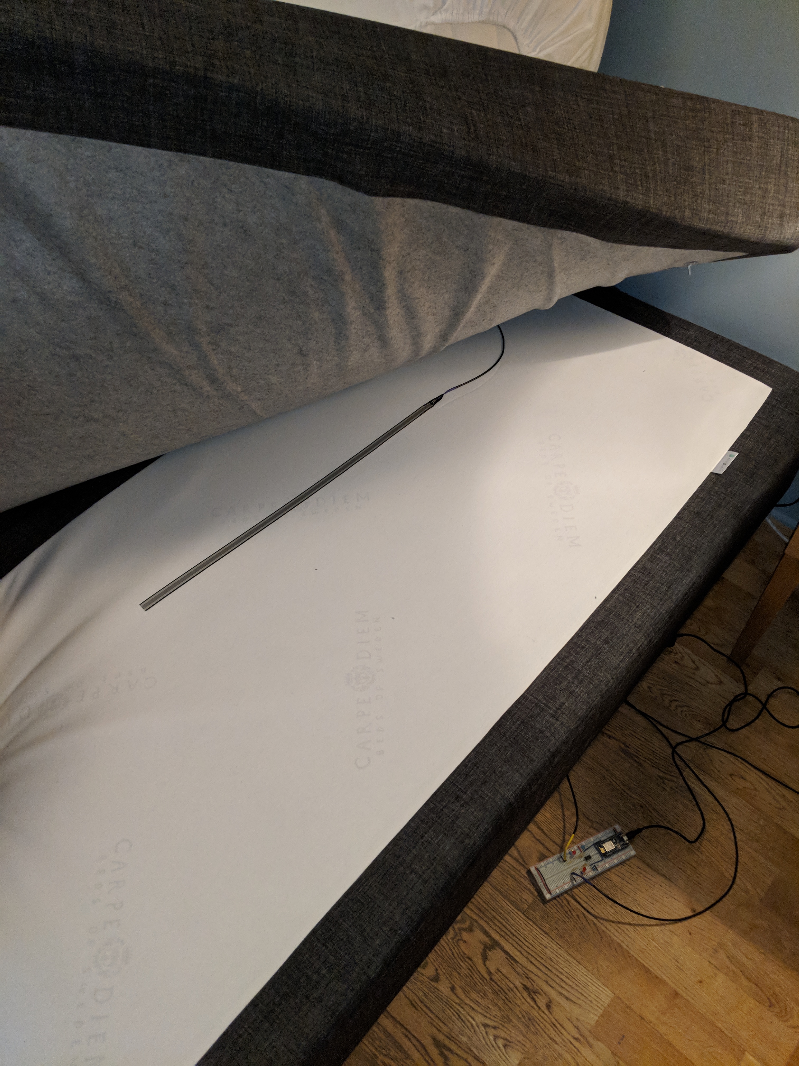
This is where I put the FSR in the bed.

Voltage divider
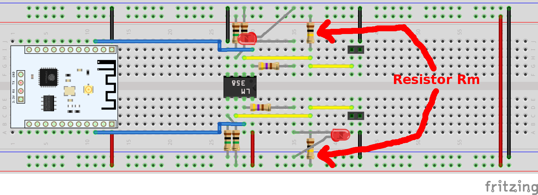
The FSR will change resistance depending on how much force that is applied. We need to change this Ohm to Voltage in order to get a signal that we can read. We do this using a voltage divider. To find out how large the Rm should be, I simple put the FSR in between my mattresses and measured the resistance when I laid in bed. This value will very much depend on the bed, the weight and your size. I ended up measuring 100k Ohms as the sweet spot when someone was in bed, which was true for both my partner and I.
The Op Amp that will act as a comparator will trigger on 2.5 V, which means that we want the voltage divider to read 2.5 V when we're at the trigger point. This means that the Rm for my project will be 100k Ohm.
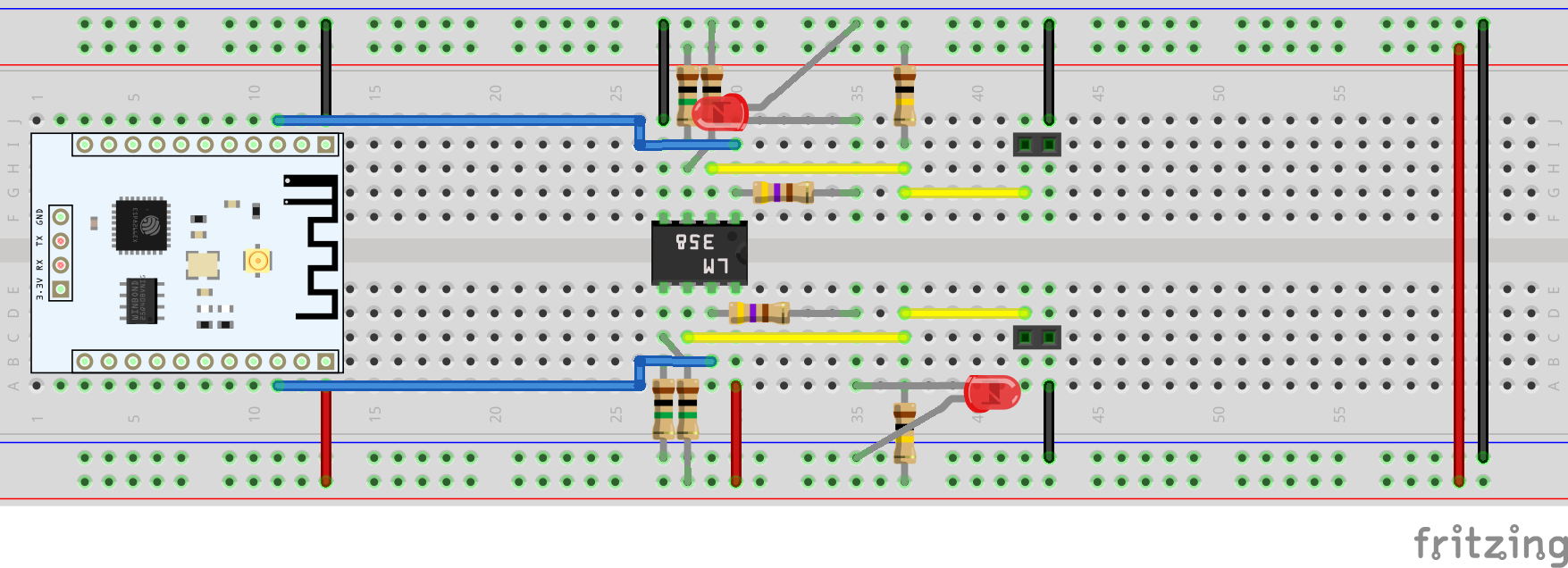
We simply connect the FSR between Vcc and our measuring point, and then the Rm between the measuring point and Gnd, as shown in the layout below.

Comparator
The comparator is built on an op amp, in my case the LM358, since I had one laying around at home. To use an Op Amp as a comparator we feed the In- with Vcc/2, the In+ with the output of the voltage divider, and then the output will essentially be a step output between Gnd and Vcc whenever the voltage divider crosses the Vcc/2 point.
The Vcc/2 is wired by a simple voltage divider with R1 and R2 being equal. You can use any resistors you want, I happened to have a few 1M Ohm resistors so I used those.
The LM358 is a dual op amp, so we can connect both FSRs to this since I'm going to use one for each side of the bed.
ESP8266
So we now have the output which will be a 5V when someone is in bed, and 0V when it's empty. This will be wired to two GPIO pins on the ESP386. We can use any pins except 16, so in this example I use pin 4 and 5.
We wired it by simply connecting the output of the two Op Amps into pin 4 and 5 respectively.
On Board LED signals
If we want to we can add LEDs to the breadboard to get a visual signal when the sensor is triggering.
We do that by adding a simple Resistor + LED to each output.
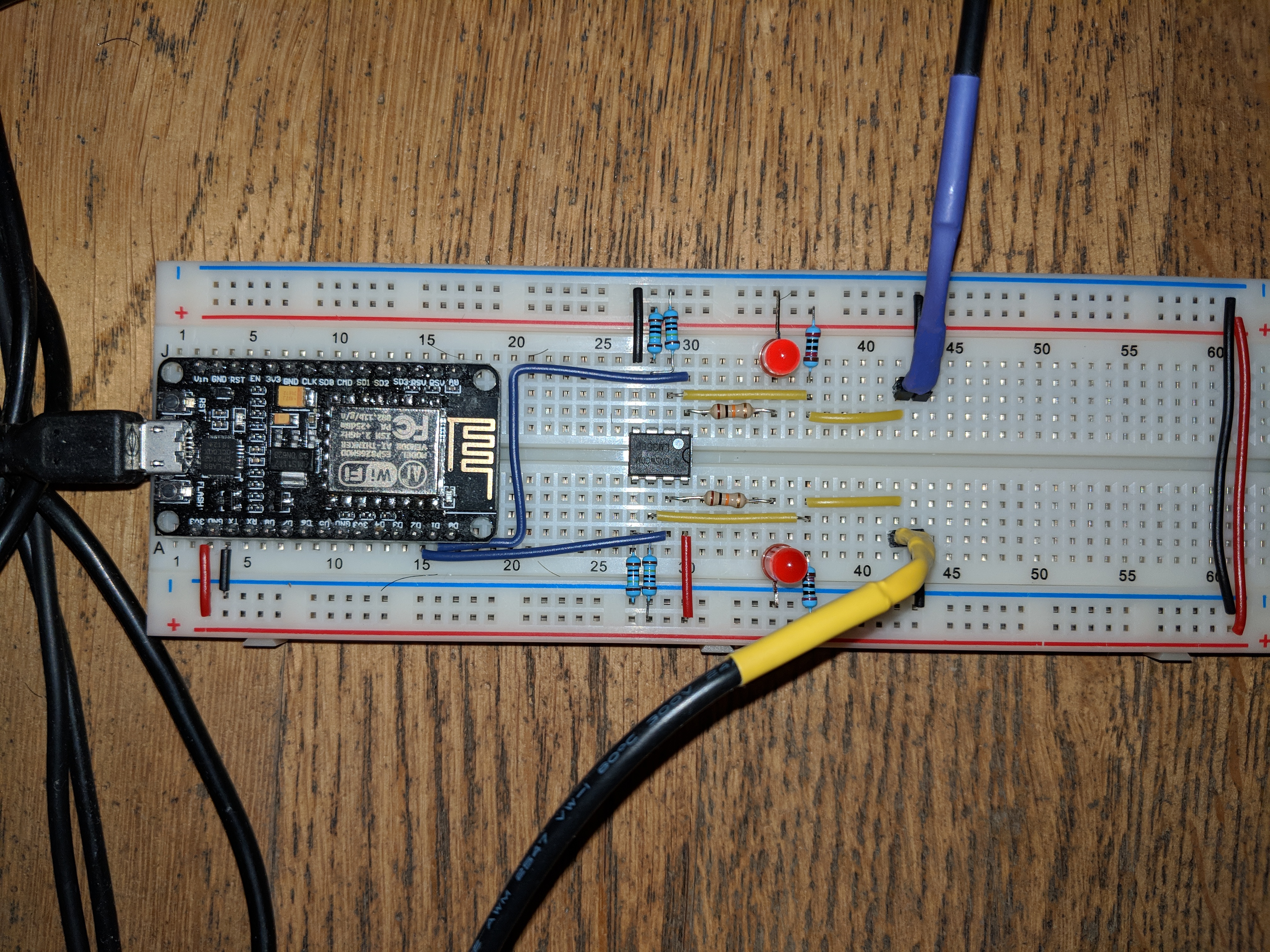
The end result on a breadboard can look like this.

Sensor code
First we give a couple of configuration variables, such as the SSID and password for the WiFi, the path to the MQTT server and the MQTT topic.
#include <ESP8266WiFi.h>
#include <PubSubClient.h>
#include <ArduinoJson.h>

const char* ssid = "WiFi Name";
const char* password = "password";

const char* mqtt_server = "mqtt_host";

const char* mqtt_topic = "sensor/bedoccupancy";

#define Bed0Pin 5
#define Bed1Pin 4

volatile byte interruptCounter = 0;

WiFiClient wifi_client;
PubSubClient mqtt_client(wifi_client);
Then we configure the Serial logger, the WiFi, configure the pins to be input + interrupts, and specify the interrupt handler.
void setup() {
  // put your setup code here, to run once:
  pinMode(LED_BUILTIN, OUTPUT);
  Serial.begin(115200);
  setup_wifi();
  setup_mqtt();


  pinMode(Bed0Pin, INPUT_PULLUP);
  pinMode(Bed1Pin, INPUT_PULLUP);
  attachInterrupt(digitalPinToInterrupt(Bed0Pin), handleInterrupt, CHANGE);
  attachInterrupt(digitalPinToInterrupt(Bed1Pin), handleInterrupt, CHANGE);
  digitalWrite(LED_BUILTIN, HIGH);
}

void setup_mqtt() {
  mqtt_client.setServer(mqtt_server, 1883);
}

void setup_wifi() {
  delay(10);
  Serial.println();
  Serial.println();
  Serial.print("Connecting to ");
  Serial.println(ssid);
  digitalWrite(LED_BUILTIN, LOW);
  delay(100);
  digitalWrite(LED_BUILTIN, HIGH);

  WiFi.mode(WIFI_STA);
  WiFi.begin(ssid, password);

  while (WiFi.status() != WL_CONNECTED) {
  digitalWrite(LED_BUILTIN, LOW);
  delay(100);
  digitalWrite(LED_BUILTIN, HIGH);
  delay(400);
    Serial.print(".");
  }

  Serial.println("");
  Serial.println("WiFi connected.");
  Serial.println("IP address: ");
  Serial.println(WiFi.localIP());
}
We want the interrupt handler to be as quick as possible, so we only increase the interrupt counter here and handle the actual reading and publishing in the main code.
void handleInterrupt() {
  ++interruptCounter;
}
The main loop checks the interrupt counter, and if it is larger than 0, we read the signals, connect to the MQTT server and publishes our readings.
void publish(int val0, int val1) {
  if (!mqtt_client.connected()) {
    reconnect();
  }
  mqtt_client.loop();

  StaticJsonBuffer<200> jsonBuffer;
  JsonObject& root = jsonBuffer.createObject();
  root["sensor"] = "bed";
  JsonArray& data = root.createNestedArray("data");
  data.add(val0);
  data.add(val1);
  root.printTo(Serial);
  Serial.println();
  String json;
  root.printTo(json);

  mqtt_client.publish(mqtt_topic, json.c_str(), true);
}

void loop() {
  // put your main code here, to run repeatedly:
  if (interruptCounter>0) {
    interruptCounter = 0;
    digitalWrite(LED_BUILTIN, LOW);
    auto val0 = digitalRead(Bed0Pin);
    auto val1 = digitalRead(Bed1Pin);
    publish(val0, val1);
    delay(100);
    digitalWrite(LED_BUILTIN, HIGH);
  }
}
The reason to use the JSON library is that I simply wanted to test it out. This can be as simple or complex as you want it to.
Home Assistant
So we got messages coming into a MQTT topic. We now want to create one binary sensor for each bed we're monitoring. This is done by adding a binary sensor to the Home Assistant configuration, and use the mqtt platform.
Once this is setup we can verify that it works by looking on the main page in Home Assistant, finding our new sensor and then press on the bed.
Next steps
Create scenes that reacts to this event. I created a new sensor that checks for the presence of our mobile phones, and if everyone that is at home is also in bed, it will enable. This makes it easier to create scenes that turns off all lights even if one of us is away.
Currently we have one scene that when everyone goes to bed after 9pm all lights in the apartment goes out and whatever media is playing is stopped. Then we have a second scene that if someone leaves the bed during the night a nightlight goes on in the hallway. This will not wake anyone up, but will make it easier to find your way around the apartment.
Known issues
The sensor stops working after a random number of days, which means that there is a bug in the WiFi or MQTT code. Haven't had time to find it yet, so please be aware that you may have to restart the sensor every now and then.
