@sebdetours said in  MDMSPanel "Nextion":
Did you take a standart case that you cut out?
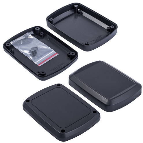
Hi @sebdetours, yes. This is G1910 (Gainta) box. See drawing attached to projet files.

Hi everyone!
It is time to publish my new project called MDMSPanel “Nextion”.
The prototype of this panel is MDMScreen, however there were more disadvantages than advantages and I had to stop its development. Thanks to everyone who put the likes.
The panel is a script controller. At the moment, it works as a thermostat. In general, the functional purpose of the panel is determined by the software loaded into it. This means that its uses is not limited ...
Features:
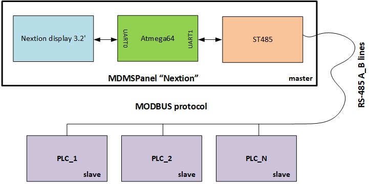
The panel interacts with any devices working under the MODBUS protocol (in plans to get it work with the MySensors protocol). Panel operates in a master mode. You can edit coils and holding registers, as well as view inputs and input registers. You can connect any devices operating in slave mode to the panel.

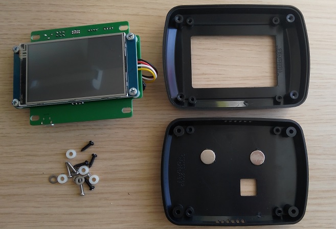
I am going to install the panel in each room, fixing it on the wall. This will allow me to manage my smart home quickly and without any gadgets. The mount is magnetic, consists of two parts - the magnets mounted on the wall, and the magnets inside the case. The distance between the magnets is 40 mm.

On the back side there is a terminal block for connecting RS-485 lines (A and B) and supply voltage.

After installation on the wall, the panel looks like this.Will only have to hide the wires in a special box or mount them in the wall.
 
Below are a couple of photos showing the device from the inside.


Stages: