MySensors AC/DC light switch
Note about the 'work in progress' status
I've created an earlier version of this board (v3.3.1) last week, and that one was working fine since then! The only difference with the board in this project (v3.3.2) is the addition of a DS18B20 temperature sensor, and some small corrections were made to the silkscreen. So I'm not expecting any problems with this newer version either. If you still want me to have this confirmed first, I recommend to wait a little longer.
Goal
The main goal for this project was to come up with an easy, simple to integrate solution to control the lights in the house. When designing this solution, I wanted to meet the following requirements:
- Easy to integrate in the existing electricity grid.
- Lights should always be controllable by the normal light switch too.
- As I wanted to control all the lights in my house (and a lot of nodes will have to be assembled), it should be cheap as well (Target was 10 Euro per node).
- Completely powered by the grid, and not by batteries.
- It should be safe to leave it running for years and years without the need for further attention.
Solution
With the great help my MySensors.org , I have designed a small PCB of 50mm by 50mm. Because of this small size, it is even possible to place this custom PCB behind a light switch.
The PCB is designed to fit following essential components:
- HLK-PM01 as an AC to 5v DC converter
- Arduino Pro Mini
- NRF24L01 or NRF24L01+
- Fuses, temperature cutoffs, and varistors to secure the circuit
- Capacitors to provide stable voltage to the Arduino and NRF24L01 module
- 2x 2A solid state relay
- A temperature sensor to monitor the temperature of the PCB.
- Screw terminals to provide power to the PCB and to connect the solid state relays.
- 2x 2 pins to connect the light switches to the PCB
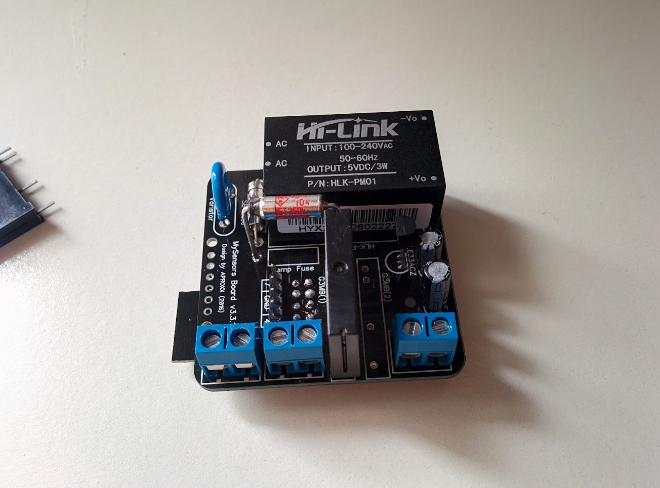
The end result looks something like this:

These boards are available via DirtyPCBs
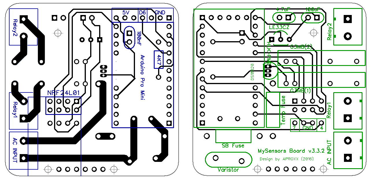
PCB layout
Bottom side, Top side.

How to assemble the board
Because of the small footprint of the board, it’s important to mount all the components in a specific sequence.
Before mounting everything to the board, make sure all the components are working properly. Check if the fuses are still ok, flash your Arduino,..
It’s advised to mount the components in following order:
- Solder the temp fuse very quickly to make sure it doesn’t burn. Check with a multimeter after you finished soldering this temp fuse to make sure it’s still conducting.
- Continue by reinforcing the traces between the connectors and the relays. To make sure the 2A doesn’t burn the board, it’s recommended to reinforce these traces by adding some solder to it.
- Solder the 4 pins (7 - GND - GND - 4) on top of the board. You can use the Arduino 6-pin header for this if you like.
- Solder the NRF24L01 on the bottom side of the PCB.
- Mount the connectors for AC INPUT, RELAY1 and optionally RELAY2 on the top side of the PCB.
- Mount the G3MB Solid State RELAY1 and optionally RELAY2.
- After this is done, add some tape or other insulating material to cover the traces between the connectors and the relays.
- Then solder following components in any order: LE33ACZ, 3 capacitors(Make sure to solder the 100nF capacitor sideways, so the Arduino can be placed on top of it), Slow Blow Fuse, Varistor.
- Solder the Arduino headers on the board, but not the Arduino itself! The Arduino will be installed after the HLK-PM01 has been installed. Only the 2.54mm pins need to be soldered onto the board at this stage.
- On the top side, put the HLK-PM01 AC/DC converter in place and solder it to the PCB.
- After the HLK-PM01 is installed, continue soldering the Arduino on the headers on the bottom of the board (Make sure the Arduino is oriented properly!).
How to connect the board behind a light switch
As seen on the picture below, the light switch is no longer connected to the AC Circuit. The light switch now serves as an input to the Arduino, after which the Arduino will close the relay and turn on the lights. The optional 2nd relay can be connected in the same way as relay 1.

Version history
3.3.2
Known issues: None.
Fixes:
- Added some spacing between the high voltage (110v or 230v) and 5v traces. Just to be on the safe side in case the boardhouse delivers low quality PCBs.
- Relay2 output connector moved by 0.5mm to the outside of the board. Relay 2 and the matching connector were a bit close to each other.
- Polarity on 100uf and 4.7uf capacitor pads has been reversed/corrected.
- Silkscreen for the LE33 has been reversed/corrected.
New Features: DS18B20
3.3.1
Known issues:
- Polarity on 100uf and 4.7uf capacitors are reversed. Minus should be soldered to the round connector, and the plus side of the capacitors should be soldered to the square connector.
- Silkscreen for the LE33EZ is reversed. The LE33EZ should be placed on the board the other way around.
Fixes:
New Features: /


